It started with replacing the sole and ended with casting molten lead
Issue 38 : Sept/Oct 2004
Not long ago I was reminded about how a small job can turn into a much larger one. My 1976 Chrysler 26 Swing Keel had a small hole in the sole under the companionway ladder. Armed with a long-handled screwdriver to use as a prybar, I decided to do some excavating to see how much floor needed to be replaced. The soft rotted plywood around the hole came up easily in delaminated sheets . . . as did the rest of the floor. Water had been soaking the plywood for many years. The forward end of the sole extended under the spruce beam that supports the deck-stepped mast. Unfortunately, this meant that the mast had been poorly supported on soggy layers of rotted plywood. It all had to be replaced.
Chrysler 26s with the swing keel have 1,200 pounds of lead ballast installed in a shallow “shoal keel” and an 800-pound centerboard that can be raised into a housing that occupies the center of the main cabin. The keel housing is a fiberglass structure with plywood glassed onto each vertical side for support. The plywood supports extend all the way to the bottom of the shoal keel, which is filled with about 240 (or so) 5-pound lead ingots encapsulated in brittle urethane foam.
The foam and lead looked dry, but when I stabbed the brown foam with a screwdriver, it squirted water. It was saturated. The boat had no obvious leaks. Other than the rotted floor, the rest of the boat was dry.
The outside perimeter of the cabin floor rests on the hull. Some lengths of aluminum angle screwed into the keel housing stiffeners provide support for the other side of the floor. I used these pieces of angle as a reference to locate points where the new floor would contact the hull.
Rotating laser
Using the aluminum angle as a reference and a rotating laser pointer, I drew two perimeter lines on the hull, one representing where the bottom of the 3⁄4-inch plywood floor would intersect the hull and the other just above it where the top would be. By locating both lines, I could taper the edges of the floor to match the angle of the hull. This perimeter line was then converted to offset measurements that could be used to cut out the new floor panels.
Just like the rotted floor, the plywood supports on either side of the keel housing were showing signs of delaminating. It was not obvious this was the case until the carpet covering the keel housing was removed. At this point I was still trying to decide just how large a project I wanted to tackle. I could ignore the delaminated plywood on the keel housing and just put in the new floor, or I could tear out the lead ballast and wet urethane foam and replace the stiffeners also. I was more concerned about where the water that had saturated the ballast area was coming from than I was about the poor condition of the keel housing stiffeners. Using a long narrow prybar, I popped out a few lead bricks to get a feel for how hard it would be to remove them all. The first few came out deceivingly well, so I forged ahead. As each layer of bricks was removed, the foam became denser and harder, and the hull forming the inside of the keel became narrower. Removal of the ballast became more difficult with each successive layer.
Eventually though, all the lead and urethane on each side of the keel housing was removed as far forward as I could reach under the cabin liner. Next I removed both of the keel-housing stiffeners. While peeling the wood from the fiberglass housing, I kept one side as intact as possible. I used this piece later as a template for the new stiffeners. The lower part of the stiffeners that sat low in the hull had become delaminated and came off easily, but the plywood on the upper housing was still intact and required some careful chisel work to clean it from the fiberglass housing. I cleaned and sanded all the fiberglass surfaces and placed electric heaters at each end of the keel area to help it dry out.
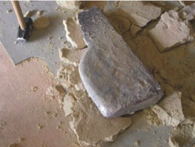
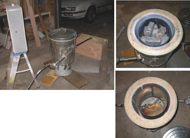
compactly as they had been placed the first time, Jim made plaster of Paris plugs, buried these in hard-packed sand, and poured molten lead in the cavities they left behind. One of these lead castings is shown, above right, free of the mold. He needn’t have worried about the space in his keel: the new ballast sits 2 inches lower than the original did.
Leaking bolts
After all of the wood was removed and the glass cleaned up, the search for the cause of the wet ballast began. It appeared that the bolts holding the pivot-pin housing to the hull had permitted water to leak into the ballast area. They came up through the front of the shoal keel and threaded into steel plates embedded in the fiberglass. After I had run the heater for several weeks, I sanded the steel plates and the surrounding glass and applied a layer of epoxy thickened with fumed silica to seal the area against further leaks. Another layer of unthickened epoxy would be added later to encapsulate the lead ballast.
The floor that was removed from under the liner just ahead of the keel served as the main support for the deck-stepped mast. At the factory, the original floor could extend under the mast because it was installed before the liner was installed. I needed to fabricate a mast support platform to replace the function originally served by the cabin floor. To increase the rigidity of this support and spread the load of the mast over a larger area of the hull, I used two layers of 3⁄4-inch plywood. These pieces were cut to fit so that their contact with the hull would be as large as possible. The support boards were about 8 inches front-to-back and as wide as I could fit them under the liner. I carefully tapered the sides of the boards to match the angle of the hull. They were sealed and glued to the hull with thickened epoxy. The space above the support boards and under the liner was filled with several layers of plywood to provide a solid platform for the mast.
Using the old plywood stiffener that was saved for a template, I cut two pieces of 3⁄4-inch plywood to match and coated them with unthickened epoxy to seal them against moisture. Then I used thickened epoxy to glue them onto the keel housing. I used large C-clamps on the top of the assembly and forced scrap wood strips between the settees and the plywood to clamp the bottom.
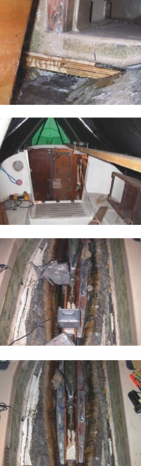
Little clearance
There was only an inch of clearance between the floor and some of the lead bricks. Concerned that the bricks might not fit as compactly as when they were originally installed, I decided to cast 1,200 pounds of lead bricks into 10 large form-fitting pieces. Installing the lead ballast as solid castings, as opposed to bricks encapsulated in foam, should improve the performance of the boat by putting the ballast weight at a point lower than it had been originally. To create the lead castings, I fabricated plaster of Paris patterns of the hull, a furnace, a melting crucible, and a mold box. (See the sidebar on Page 33 about building a furnace and casting the lead ballast.)
I used a pair of pulley systems to get the castings into the boat. With the boat on its trailer, the castings had to be raised 10 feet in order to get them into the cockpit. I used a block and tackle to get the castings from the ground into the boat and a pulley/trolley system to move them across the cockpit and into the cabin. Each casting was pre-fitted with a piece of aluminum angle for an attachment point that would be removed after it was installed.
After the castings had been lowered into their respective places in the hull, I taped cardboard dams in place to contain the epoxy fore and aft of the castings. After several pours, the ballast was permanently encapsulated in solid epoxy.
Even though I added an additional 180 pounds of lead to the castings, the new ballast sits 2 inches lower in the hull than it did as originally installed. Up to 400 pounds of additional ballast could have been added with the space that was gained. The area between castings was filled with lead shot and epoxy. That added an extra 25 pounds of lead to an area that would otherwise have been filled with epoxy and filler.
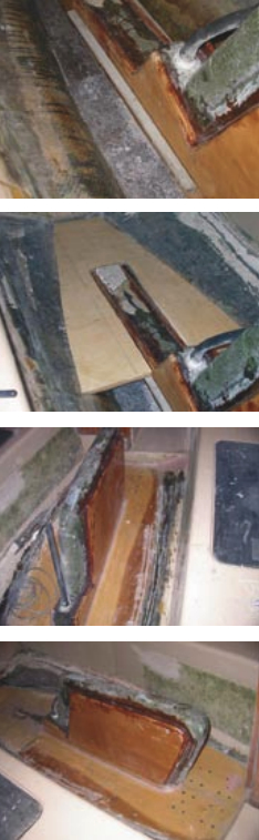
Installing floor
After installing the new keel stiffeners and ballast, the next step was to install the new floor. I cut 3⁄4-inch plywood to match the offsets that I had recorded previously using the laser pointer. I cut one panel for the floor aft of the winch cable and two pieces (port and starboard) for the rest. Using an angle grinder, I tapered the outside edge of the panels so they would sit flat against the hull. When the panels were placed in the boat for a test fit, the reason for taking the extra time to measure the perimeter for both the top and the bottom of the floor became obvious. They all fit surprising well. The tapered edge of the floorboards matched the angle of the hull perfectly.
The forward floor sections needed a means of providing additional support between their mating edges. I cut a piece of 1⁄4-inch aluminum plate to bolt beneath the joint. Because there was no access under the floor panels, I drilled and tapped the aluminum plate for 1⁄4-inch x 20 flathead screws. The aluminum angle that supported the floor next to the keel housing was replaced with 1-inch x 1⁄8-inch stainless angle. I glued all three of the floor panels in place using thickened epoxy and the 1⁄4-inch screws. After the epoxy had hardened, I leveled the gaps between the aft panel and the keel housing and the union between the floor panels and the liner at the fore and aft ends with polyester body filler. I rolled out 3-inch glass tape on the inside and outside perimeter and saturated it with epoxy. The result was a sealed, sound, and flat floor.
Thank you to Sailrite Enterprises, Inc., for providing free access to back issues of Good Old Boat through intellectual property rights. Sailrite.com