Installing an inboard engine in a boat that never had one
Issue 50 : Sept/Oct 2006
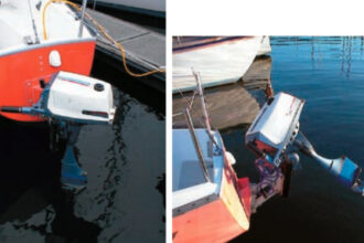
Some sailors are hypocrites. I’m a hypocrite. We profess to believe in the power of the wind, yet few of us go sailing without taking an engine along for the ride. When the wind poops out, we take down the sails, crank up the motor, and become captains of inefficient motorboats. Sailing, with the sound of the breeze in the rigging, gives us a sense of freedom. Unfortunately, if the engine is broken many of us will forgo that sail . . . which only proves how dependent we are on a reliable power source.
David Buckman, owner of the 26- foot International Folkboat, Leight, had suffered the inefficiencies of outboard motors long enough and wanted a reliable inboard diesel (see article on Page 18). This installation became one of my projects at Padebco Custom Boats in Round Pond, Maine. David had considered selling Leight and buying a 32- to 35-footer, but he concluded that an older boat in his price range would undoubtedly come with an old and unreliable inboard engine. He decided to keep Leight, which he had been contentedly modifying for the past 20 years.
Installing an inboard motor was a good compromise, but it wasn’t going to be cheap. An engine is a hub, around which the financial terrors of a complete installation take place. The cost of the new Yanmar 1GM, one-cylinder diesel would represent just a third of the total bill. Considering it would take 95 hours to install, labor would equal the price of the engine. The scores of necessary parts would absorb the remainder.
Challenges galore
Placing an engine in Leight, a boat that had never had an inboard installed, presented a multitude of challenges beyond those met with engine replacement. Her narrow beam, low cockpit floor, and sealed lazarettes would make access difficult. And, with a keel-hung rudder, some serious cutting would be required to create an aperture for the propeller. Initial measurements indicated that tolerances would be tight, but possible. With careful planning and a clear vision of the final installation, it would all fit together. Somehow.
When I first began fooling with engines two decades ago, my knowledge of diesels culminated with the question, “Where are the spark plugs?” Over the years I’ve taken classes, pulled engines out of boats for repair, installed replacement engines, built new engine bed risers, and replaced fuel tanks, exhaust systems, water systems, and electrical systems. I’ve seen nightmarish engine rooms and others that are logical and organized.
To avoid creating a nightmare, you must ask yourself at each step: “Is this the best way? What will happen when I begin the next phase, and the phase after that?” Keep thinking this way because it doesn’t matter how large the engine room is, there are going to be a lot of hoses and wires crammed into a small space. The cleaner it’s done from the onset, the easier it will be to maintain and fix. Every step of the installation must come with a sound reason for doing it that particular way. Use logic, not guesswork.
First, build models
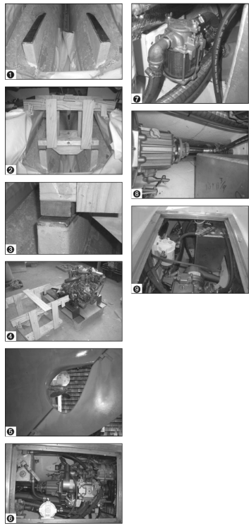
The best way to determine the location of new engine bed risers is to make an accurate wooden jig of the engine (see sidebar on Page 17). Without a jig, the territory known as guesswork looms large and bleak. Designing and building the risers on Leight presented a typical three-dimensional enigma since the hull under the engine was a curved, tapered wedge. My plan was to suspend the jig in position above the hull, then create the risers by simply filling in the void between the bottom of the jig and the hull. To do this, I would use polyisocyanurate foam (which is easy to cut and sand and is impervious to resins). The polyiso foam would act as a mold over which I would lay ample fiberglass.
To orient the jig, I had to know where the shaft would exit the hull. To do that, I had to know where to cut the aperture. There were two gudgeons on the keel below the waterline. I wanted the shaft to end up below the top one by at least 4 inches so I could cut and then fiberglass without having to remove any hardware.
The tips of the 14-inch Max-Prop propeller would need at least an inch of clearance from the aperture, so I measured down 8 inches to locate the center of the shaft (1-inch clearance, plus half the prop diameter, equals 8 inches). This put the top of the propeller about 20 inches below the waterline, a good distance to prevent cavitation in a pitching sea. I drilled a 1⁄4-inch pilot hole to view the location from inside the bilge. What concerned me now was the downward tilt of the engine. Specifications allowed a maximum 15 degrees, so I held the jig in place temporarily, put the fiberglass rod over the pilot hole, then determined that the angle was 8 degrees.
Start with what’s known
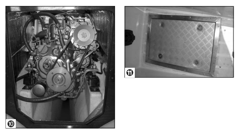
To choose the optimum location for the engine, I started with the known. The forwardmost-protruding part of the engine was the belt pulley driving the alternator. I wanted 2 inches between it and the existing access door under the companionway to allow room for soundproofing insulation. There was no point in crowding the door, then being forced to make unnecessary woodwork alterations later on. This left less than 2 inches between the top of the engine and the bottom of the cockpit floor. Not much room for working on the engine, but the plan was to install an inspection hatch in the cockpit floor.
I removed the fiberglass rod and replaced it with string. I tied one end to the back of the keel and ran the other through the two holes in the jig. The string guaranteed that the jig would not be twisted, cocked, or off-plane. I fastened the jig into position by hot-gluing it to two sticks that spanned the quarter berths. I made chocks for these sticks to sit in so I could take the jig in and out without having to re-measure or fiddle with the string again. Now that I had found the ideal location for the engine, I tried to find reasons why it wouldn’t work.
I took the Vetus exhaust water trap in hand and held it in place behind the jig. I envisioned the heavy hose coming off the engine manifold and the exhaust hose going to the transom. Was there room? Due to the narrow contour of the hull behind the engine, I observed that the water trap would have to sit on the shaft in order to be low enough for proper drainage. That meant the fiberglass stern tube needed to be long enough so the trap could rest on top of it without worrying about the spinning shaft. I measured the length required for the shaft coupling, for the PYI dripless stuffing box, and for a few inches of bare shaft (this, so you can slide the coupling away from the flange when moving the engine or when adjusting the stuffing box). So far, so good. I speculated about where I would put the water strainer, fuel filter, and fuel tank. If the inspection hatch were large enough, access to those items would be adequate.
There were two types of inspection hatches worth considering: the plastic $80 Bomar version and the $350 stainless and aluminum ones made by Anchor Plate. David and I discussed the pros and cons. For me, the choice was obvious, but it wasn’t my money. Plastic is plastic. Stress it and it will distort, crack, and leak. Metal is bulletproof. When I learned that David’s plans included offshore sailing, where the likelihood of filling the cockpit with an errant wave is high, I said, “Imagine you are hundreds of miles from land, with a storm raging, and sea water is raining down through your inexpensive cockpit inspection hatches. You will be pumping the bilge every 15 minutes and hoping the engine is not getting ruined. At that point what’s the use of the $270 difference?” David chose the metal.
I actually installed two hatches: a large one and a small one. Because the scupper seacocks were way under the cockpit, access to the seacocks would be impossible without the addition of a small hatch. This hatch would also provide access for installing the exhaust system and it would open up new storage possibilities. I cut the holes in the cockpit floor for the hatches but chose not to install them until the end of the project.
Someone’s gotta do it
The next step was possibly the worst: grinding fiberglass under the cockpit. I donned my hooded paper suit, taped rubber gloves over my hands, fitted my charcoal respirator and ear muffs, then put a big suction fan in the cockpit. Using a 4-inch angle grinder with 36-grit, I sanded away all the aged gelcoat in what was to become the engine compartment. (It wasn’t as bad as the time I cut old risers out of a boat with a chain saw, but that’s a different story.)
One of the downsides to using foam instead of wood for risers is that foam will not hold the lag screws required for securing the engine mounts. Bearing that in mind, I placed a 2-inch-wide, 3⁄8-inch-thick mild steel bar on top of each riser prior to laminating. After the engine was in place I would drill and tap and then secure the mounts using machine bolts.
With the jig in place, I cut the foam using a handsaw and glued it to the hull with Polyfair, a quick-setting fairing compound similar to Bondo. I calculated that the fiberglass would add 1⁄4 inch to the circumference of each riser. This meant the gap between the risers would decrease by 1⁄2 inch, a substantial amount considering the closeness of the oil pan to the forward starboard engine mount. I adjusted all measurements so the final layup would not have any compromising effect. After the fairing goop hardened, I removed the jig, filleted the crevasses, and filled in some voids for a smoother layup surface. Next, the fiberglassing.
Using sheet plastic, I made patterns so I could cut the fiberglass cloth on a table next to the boat. Fiberglass is miserable stuff. Although cutting with scissors is silent — and seemingly harmless — it is just as toxic as the dust from grinding because the dry glass fibers break into shards and drift around like airborne barbed wire. These miniscule shards are nearly impossible to remove and will contaminate a cabin and your clothes (not to mention your lungs). Another good reason to pre-cut is there’s nothing worse than using scissors while wearing sticky, resin-covered gloves. You quickly become the modern version of tarred and feathered as the fibers knot around fingers, scissors, and everything else that’s touched.
An accurate pattern, combined with careful cutting, creates a more professional job. Anyway, I would rather be fastidious in the layup and have little or no grinding to do later. For the layup I used four layers of 1 1⁄2-ounce chopped strand mat, alternating with three layers of 18-ounce woven roving. I cut each schedule (one mat, one roving) smaller than the one before it by about an inch so edges would feather. Working smallest to biggest, the last lamination would be a single layer of mat to cover the last layer of roving. For resin, I used epoxy-based vinylester, which has a higher bonding rate than regular polyester resin but is much easier to work than straight epoxy.
Another way to keep the mess to a minimum is to pre-wet each layer of cloth on a flat piece of cardboard before bringing it on the boat. This creates a few more trips up and down the ladder, but better results are attained because the resin can be rolled on evenly right to the edge of the material without gravity working against it.
Chopped strand mat is tricky. Over-saturate or wait more than a minute, and the chemical that bonds the fibers dissolves, leaving a soggy mass of goo that sticks to the cardboard. Working quickly, you can wet the mat out, peel it off the cardboard, and still get it into position while it’s relatively stiff. The trick is to pre-wet just enough so you don’t need to brush on any more resin at the boat. As soon as the mat is tucked into place, add the pre-wetted woven roving. Always use a ribbed bubble roller to smooth out the cloth and displace air. Dabbing with a brush is OK for deep corners, but the fewer air bubbles, the higher the quality.
After the lamination kicked, I scuffed away a few burrs with 80-grit sandpaper, wiped with acetone, then applied two coats of gelcoat (polyurethane paint also works, but gelcoat is bulletproof). Next, I began cutting out the aperture, a little at a time, while checking the size with a plywood silhouette of the propeller. (The plywood was much easier to use than the heavy and awkward feathering Max-Prop propeller). Using a grinder, I tapered the rough edge of the aperture to a fine point. I would do a thin layup on the outside of the hull to get the shape, then do a robust layup inside to get the strength.
In she went
A one-cylinder diesel is not much heavier than a 15-hp outboard, so it was easy for two of us to carry the engine up to the cockpit and put it in place. I re-checked measurements, then drilled a 11⁄2-inch hole in the back
of the new aperture, slid the shaft through the hole, and bolted it to the engine. I slid the stern tube into position. The hole was slightly oversized so I could be certain the tube was not in a bind. I shimmed it to dead center.
Next I loosened the shaft coupling bolts and checked the alignment with a feeler gauge. My concern was that the weight of the 4-foot shaft tended to hog the back of the engine downward on its rubber mounts and raise the front, affecting alignment. I retightened the coupling and tabbed the stern tube into position with just a little bit of fiberglass and then added a gusset to support the shaft just behind the stuffing box. I again checked the alignment and tightened everything up. Perfect.
I made a big fillet around the stern tube with polyester hull-and-deck filler, then built up layers of fiberglass over it. It is very important to glass the stern tube with the shaft inside it to be certain everything remains aligned. (The Cutless bearing centers the back of the tube over the shaft, but shims are required to center the forward end.)
With the shaft and stern tube in position, I calculated where to cut the shaft so that when the propeller was installed there would be enough room for a collar zinc, plus an extra 1⁄4 inch of open shaft to prevent the zinc from rubbing against the tube under full thrust. When I thought I had it right, I double-checked my measurements, then sent the shaft to a machine shop for the final cutting. After I got the shaft back, I installed the propeller and cut the aperture into the rudder.
Putting the pieces together
A successfully installed fuel tank, fuel filter, water strainer, and shift lever control means that mechanical function and accessibility have been given equal consideration: if a component can not be maintained or repaired easily, the entire system will fail. On a small boat like Leight with limited space, however, function must sometimes overshadow accessibility if the components are to work at all. I scrutinized locations and chose the lesser evils in each instance.
Fuel tank – A small fuel tank that is the right shape is often more useful than a large tank of the wrong shape. I wanted a tank that was tall and narrow and oriented fore and aft so that when the boat heeled, the fuel standpipe would not suck air when the fuel level was low. It would have been possible to get a larger (wide and flat) tank in place, but when a wide tank is half full, the fuel sloshes to the corners, increasing the risk that the pipe will be high and dry. The tiniest suspicion of air in the line can stop a diesel engine cold.
There were three fuel tank options: plastic, metal, or collapsible rubber. I was against the collapsible for reasons of durability but had an open mind toward plastic. Unfortunately, there were not any off-the-shelf plastic tanks that fit Leight’s dimensions, in part because the fittings were in awkward positions. We decided to maximize efficiency and have an aluminum tank fabricated.
I made a mockup of the tank with hot glue and luan plywood. To fit the shape of the hull, the bottom of the tank sloped down toward the engine. The draw tube was in the deepest part, which also put it close to the engine. Alongside the draw tube was the return fitting, an electronic fuel gauge, and a plugged, 1⁄2-inch hole to be used for hand-pumping water from the tank. All of these fittings were accessible through the inspection hatch. The vent was at the opposite end of the tank, accessible through the small hatch.
Fuel filter – Ideally, I like to place a fuel filter where it can be viewed easily, such as in the head or just behind a locker door. Unfortunately, it had to go behind the engine and was almost un- viewable unless the inspection hatch was out. Even then you had to stand on your head to view the glass bowl. But with the hatch open, changing the filter element was easy. Its location also kept fuel lines short and near the fuel tank shut-off valve — which is a handy feature when changing the filter.
Water strainer – For best results, a water strainer must be mounted below the waterline. I placed it next to the seacock and alongside the fuel filter, which gave it the same advantages and disadvantages as the fuel filter.
Controls and compression shut-off knob – There are all kinds of great places to install the shift lever controls and compression shut-off knob . . . that is, until you start planning how to get the Teleflex cables to them. On Leight, they were mounted on the side of the cockpit under the tiller. The question was whether they should be in the way of the helmsperson or the crew. We decided that the helmsperson moved less than the crew and was less likely to trip over the cables during maneuvers. It was also easier to get the cables to that location.
Never install the levers first and assume the cables will get there on their own. First, observe where the cables leave the engine and how they will take corners. Sometimes moving the shifter placement an inch or two or switching sides of the cockpit can eliminate excessive hole cutting or impossible situations. I always do a dry run with a cable that is too long. (I have an old one for this purpose.) If the route works, I now have a precise measurement for length. Using rope or a tape measure can yield huge inaccuracies. In tight spaces with sharp bends, reducing or increasing the cable length by as little as a foot can make a huge difference.
Engine electrical panel – This needs to be in a place where it won’t get kicked. On Leight, David built the panel into a fiberglass box and made an acrylic cover, which was attached with Velcro.
Aftermath
When Leight was launched this spring, I stood in the cockpit with David and his wife, Leigh, as they prepared for a sea trial. I tried acting calm, but my heart was in my mouth. They had just written a substantial check to the yard and, if for some reason the engine placement and all the other components failed to work in harmony, I would be in the market for a new paddle. David barely had to turn the key before the engine bounded into life. Off they went.
The next day I watched as they sailed expertly off their mooring. They sailed back onto it again the next day. Later I asked, “How is the new engine working out?”
“Great!” David said. “We didn’t have to use it at all!”
Thank you to Sailrite Enterprises, Inc., for providing free access to back issues of Good Old Boat through intellectual property rights. Sailrite.com