Food-safe epoxy makes potable possible
Issue 65 : Mar/Apr 2009
At the end of a two-year search for a fixer-upper cruising boat, I acquired a Pearson Vanguard, hull #142 built in 1964. I found her in a boatyard in Cocoa, Florida. The previous owner said she had been out of the water for five years; yard workers said she had been there for more than 10 years. One thing for sure was that the cockpit scuppers had clogged with leaves, and accumulated rainwater had flooded the cabin. There was evidence that water had stood as deep as 18 inches above the sole, but the black and greasy water was just below the sole when I first went into the boat.
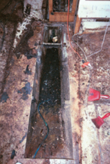
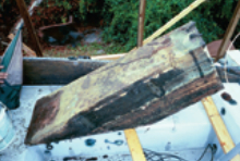
The old Monel metal water tank was shot. It was covered with oil and grime, and there were several holes along the bottom edges. Two of the rivets securing baffles had popped loose, allowing water to flow freely out of the tank. Who knows how much oil had made its way into it? The boat was going to need a new water tank.
I looked into having a tank made of medium-density polyethylene (MDP). I contacted an owner of a sister ship who had an MDP tank. His tank cost him a couple of hundred dollars, but that had been several years earlier. I contacted the tank manufacturer to ask. They needed scale drawings, which I faxed to them. The company’s quote for a new MDP tank was more than $600. I shifted my research for freshwater containment methods to a DIY solution.
Asked questions
I investigated integral fiberglass tanks, asking questions of local boatbuilders and owners of other Vanguards. With each discussion, I acquired bits of useful advice. The most important thing I learned during the inquiries was that one should not use ordinary epoxy resin to build a tank that will contain potable water. Further investigation revealed Oceaneering Research & Development in Pinellas Park, Florida. They were able to provide the necessary food-safe epoxies (Newlander Armor Products) to build and coat the new tank. I needed two different resins, one for building parts and the other for coating everything once it was all together.
Due to the quantity of rotten wood in the cabin, my plan was to completely remodel the saloon. I removed all the old furniture as well as the entire cabin sole. This provided lots of space in which to work.
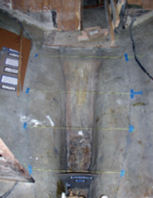
Before beginning any construction, I sandblasted the inside of the hull and bilge area. In order to lay out the tank, I first marked in the bilge the locations for the bulkheads that would form the forward and aft ends of the tank. I then divided the tank area in thirds and marked the positions for the two baffles.
Before removing it, I had marked the outline of the old sole and used this mark to establish level. I ran strings from the outline on one side of the hull to the other above the marks where the bulkheads and baffles would be placed. I measured down from the level of the sole 4 inches and placed marks under the strings at that point. I used these marks to establish the top of the tank and the actual placement of its forward and aft bulkheads and the baffles, for which I then constructed cardboard templates, drawing rough shapes and sizes and trimming them to fit with scissors. This worked very well. When made to these templates, the bulkheads and baffles required very little trimming.
Making the pieces
After fitting the templates, I started construction of the tank parts. I used a 1/4-inch thick sheet of fiberglass left over from a different project. It was just large enough to serve as the tank’s aft bulkhead. I only had to cover its inside face with fiberglass mat wetted out with the food-safe building resin. For the forward bulkhead and the baffles, I drew an outline of each template on waxed paper laid out on a flat surface. To construct them, I laid up a sandwich of two layers of heavy biaxial cloth between two layers of fiberglass mat, using the building resin.
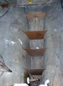
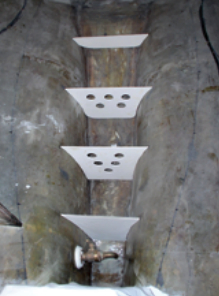
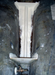
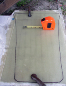
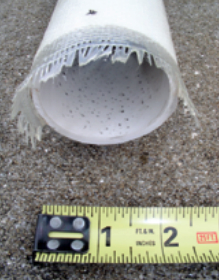
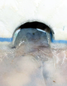
When the parts had cured, I trimmed them and took them inside the boat for a dry fit. Very little further adjustment was necessary.
Once I had made and fitted the new parts of the tank, I turned my focus to finding a way to drain any water that collected in the bilge area in front of the tank to the bilge space behind the tank. I constructed a half pipe, using 10-ounce cloth and epoxy, to create a tunnel beneath the tank. I waxed a 6-foot length of 2-inch PVC pipe and wetted out and laid glass cloth around it. Once it was cured, I removed the half pipe from the PVC mold, took it to the boat, and fit it to run down the center of the bilge under the tank. I needed to make a couple of relief cuts to get the pipe to conform to the shape of the bilge. I cut out semicircles at the bottom of the forward and aft tank bulkheads that would allow the drain to pass through them. Then I glassed in the bulkheads and drain tunnel, using the building resin. I tabbed the baffles in with 10-ounce cloth and the building resin.
A smooth and cleanable surface
Once I had glassed all the parts in place using the building resin, I covered the sides and bottom of the tank with fiberglass mat and the building resin. The texture left by the mat looked like it would provide too many places for biology experiments to get started, so I used a disc angle sander and 80-grit sandpaper to smooth it out. At this point, the tank and parts (bulkheads and baffles) were ready for application of the coating resin. I applied two coats using a foam roller. Coupled with the sanding, this produced a smooth interior surface that will be easy to clean.
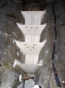
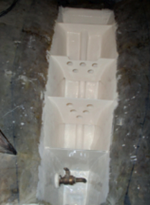
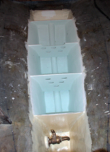
Before closing in the tank, I wanted to make sure that it could hold the weight of the water. I ran a garden hose into the boat and “filled ’er up.” I let the water stand in the tank all night and half of the next day. No leaks. I siphoned the water out and wiped the tank clean. I could begin to see the light at the end of this project’s tunnel.
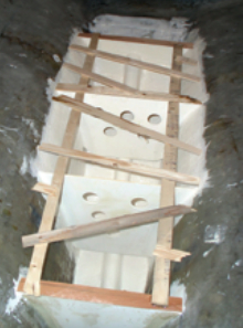
A tank has to be covered, of course. I made a template for this using a modified tick stick method. I laid two 1/4-inch by 1 1/2-inch battens (a 2 x 4 stud ripped on the table saw) parallel to each other running the length of the tank and resting on top of the bulkheads and baffles. I marked their positions and clamped them in place. I then hot-glued short battens across the two parallels so the ends of each batten just contacted the hull. I placed this series of short battens across the parallels the full length of the tank.
Connected the dots
Once all the battens were in place and the glue had cured, I lifted the web of battens off the tank, removed it from the boat, and laid it on a piece of 1/4-inch marine plywood. I marked the plywood at each corner and at the end of each short batten. When I connected the dots, I had the outline of the top of the tank. Using a jigsaw, I cut the top out at a 45-degree bevel and took it into the cabin to do a dry fit. I had to file spots at the edges so the top would sit flat on the bulkheads and baffles while touching the hull along its edges. Once I was satisfied with the fit, I covered the underside of the lid with mat and building resin, followed by a sanding and two coats of the coating resin.
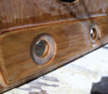
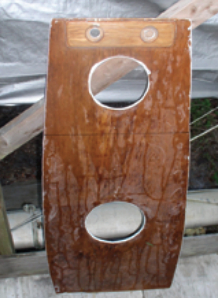
Before tabbing the top in place, I doubled its thickness at the aft end with a narrow piece of 1/4-inch marine plywood. This reinforced area would serve as a location for plumbing. I used a Forstner bit to recess the tops of the plumbing bushings. Then I drilled holes to accept the plumbing and, before permanently installing the top, cut inspection ports into it.
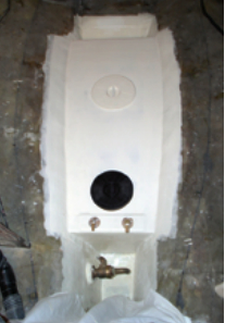
I attached the top to the tank in two steps. First, I laid down a bead of coating resin thickened with Cabosil where the edge of the top contacted the hull. I laid the top in place and then tabbed it to the hull with two layers of biaxial cloth wetted out with building resin. Once it was tabbed in place, I coated the entire top with the building resin just to tidy up its appearance.
To some, constructing this integral water tank may seem a daunting task, but actually none of the steps involved were difficult. I was relatively new to fiberglass work at the time, and the project gave me an opportunity to develop skills working with fiberglass and different types of resins.
I’m glad I decided to build a water tank in my boat and I look forward to many years of use.
Les Rogers has been a science and math teacher and football coach for 22 years. He loves sailing, and he rebuilt the Vanguard, his first boat, with his own hands so he would know it inside and out. Les and his wife, Lourdes, plan to use the boat for cruising in the summers and as a traveling home after retirement.
Thank you to Sailrite Enterprises, Inc., for providing free access to back issues of Good Old Boat through intellectual property rights. Sailrite.com