How they shape up to perform their many roles
Issue 71 : Mar/Apr 2010
When people discuss yacht design you often hear the phrase, “Well, it’s all a compromise.” That sounds defeatist to me. But if there is one area where most yacht design is certainly a compromise, it is in the design of the keel. In this issue and the next, we’ll take a look at the factors that go into designing a keel for the modern sailing yacht. We will consider the extreme ends of keel technology, but for the most part I’ll address keel design that affects the typical good old boats built in the last 40 years. I’ll touch on the technical issues, but I’ll focus on the more pragmatic aspects of keel design.
The keel has several jobs to do. It must:
- Balance the boat’s fore-and-aft trim by allowing correct ballast placement
- Provide lift to give the boat forward drive when on the wind
- Balance the forces of the sail plan and rig for easy control by the helm
- Provide a good, low home for the ballast, to ensure stability
Cruisers could add to this list the requirement that the keel needs to be of a shape to allow the boat to rest on the keel during haulouts. You can also view the keel as a protecting body that will guard the rudder, prop, and shaft from impact and help the boat deflect things like lines, logs, and rocks. I would also add that the typical good old boat keel must accommodate restrictions in draft depending upon the area were the boat is sailed.
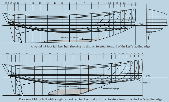
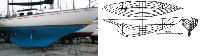
The same 45-foot hull with a slightly modified full keel and a distinct forefoot forward of the keel’s leading edge.
Defining the full keel
We are all in agreement on what a “full keel” is. For me, the full keel starts at the forefoot and terminates at the rudder gudgeon aft. We can get into arguments over what a “modified full keel” is. If the rudder is attached to the trailing edge of the keel, I think you’re looking at some form of full keel, and just how “modified” it is will be a subjective call. For convenience, let’s say that any keel with a leading edge pulled aft enough so you can see a distinct forefoot before the keel starts, and then terminates at the rudder gudgeon, is a “modified full keel” of some degree. I may use the terms “fin” and “keel” interchangeably.
In a sailboat, the keel has to provide the volume for the ballast. In some radical, high-performance, daggerboard boats today, that’s all the keel does. The daggerboards take care of the lift job. Many older boats have the ballast inside the keel fin, and I call those boats “internally ballasted boats.” If you attach the keel to the hull with bolts, I call those boats “externally ballasted boats.” As we will see, there are advantages to both approaches.
Naming the parts
Let’s start with some keel-design nomenclature. (Note: For graphical illustrations of these terms see Bob’s article in the September 2009 issue of Good Old Boat. –Eds.) The depth of the keel from the bottom of the hull to the bottom of the keel is called “span.” The horizontal fore-and-aft length of the keel at any point on the keel is called the “chord.” To describe foil shapes, the chord is broken down into percentages from the leading edge. The athwartships width of the keel is called the “thickness.” The “root” is the top of the keel where it meets the hull. The “tip” is the bottom of the keel. Leading and trailing edges are self-explanatory. When you view the keel in profile, I call the shape of the keel the “planform.” If we’re dealing with a fin keel, the fairing in of the leading and trailing edges to the hull are called the “fillets.” In sectional view, the fairing in of the fin to the hull, usually a radius, is called the “tuck” and some- times the “garboards.” Most designers use a line connecting the quarter chords — say 25 percent aft of the leading edge — to measure sweep, but for the sake of this article, sweep will be the leading-edge angle, as measured from vertical.
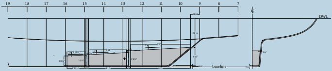
Aspect ratio is a term I will use a lot. A keel with a long chord and a short span — typical of many modern shoal-draft models — would have a low aspect ratio. If the keel has a long span and a short chord, the keel would have a higher aspect ratio. The epitome of the low-aspect-ratio keel would probably be a full-keel boat like a Westsail 32, where there is almost no distinction between where the hull ends and the keel begins. The most dramatic examples of high-aspect ratio keels would be modern racing boats like Transpac 52s with very deep fins with short chord lengths.
Aspect ratio and performance
From my perspective, there is little argument that the most effective keels in terms of performance have the highest aspect ratios. But draft is important to the cruising sailor, so we don’t always have the option of designing keels to an optimal aspect ratio. While the boat with the high-aspect-ratio fin may be a rocket to weather, if it can’t get from the slip to the bay due to shallow water, the potential performance advantage of the deep keel is a moot point.
Let’s use a 40-footer for example. A 40-footer drawing 6 feet would be considered a moderate-draft boat. I would consider anything less than 6-foot draft to be some degree of shoal draft; I’d call anything over a 6-foot draft to be some degree of deep draft. If the boat weighs 20,000 pounds, we’re going to need about 34 percent of that displacement for ballast. With all the stuff cruisers put on their boats today, the old goal of 40 percent ballast-to-displacement ratio is only achievable in boats with displacement-to-length ratios above 280, unless you go very exotic on the build materials or eliminate the interior layout and copious tankage.
Our 40-footer needs about 6,800 pounds of ballast, and the choice of either lead or cast iron for the ballast will play a major role in the shaping of the keel. Lead weighs about 700 pounds per cubic foot. Cast iron weighs about 450 pounds per cubic foot. That works out to 9.7 cubic feet for lead ballast and about 15.1 cubic feet for iron ballast. The keel designed for internal iron will require far more volume to house the ballast than the keel designed for internal lead.
You can ask the builder to use lead instead of iron for a lower ballast vertical center of gravity (VCG). But if the keel was designed for lead, you cannot substitute iron unless you are dealing with a large and voluminous fin.
The ship’s backbone
We’ll start with what we call a full keel. For years, mariners sailed the oceans upwind and down in ships that had no salient fin. The keel was a long, straight, heavy timber used to anchor the framing of the ship. It was the ship’s “backbone.” Ballast was internal. I still marvel that these vessels, usually square rigged, went to weather at all.
Over time, driven by the performance requirements of small workboats, the keel became more and more distinct from the hull and the “wineglass” section emerged as the dominant shape. The keel was dropped below the canoe-profile “fairbody” of the hull and faired into the hull sections with full garboards. Lots of examples of this shape can still be seen today. One we are all familiar with is the venerable Westsail 32. You could also consider one of my favorites, the Alberg 35, as a modified-full-keel example of this type. The long, full keel usually has a slight angle to the bottom of the keel in profile, with the forward end higher than the aftmost point of the keel. I call this the “drag angle.” There is little doubt that the true full-keel boat will take grounding with the least amount of potential damage to the hull. The problem is that the lowest point of the keel, at the aft end, is almost always where the rudder gudgeon is placed, so that fitting is vulnerable. You can remedy this by putting a slight kink, say 10 degrees, in the bottom profile of the keel to raise the gudgeon fitting up above the lowest point of the keel, as L. Francis Herreshoff did when designing Landfall.
Effects of the leading edge
Unfortunately, the keels of most full-keel boats and many modified-full-keel boats do not have good foil shapes. Many have very blunt, even flat, leading edges. In plan view, these keels often have no taper at all until just before the rudder stock. This works. Star class boats and Snipes, along with other classes, use flat-plate keels with no foil whatsoever. They sail fine, but today we recognize that choosing the correct foil results in the best performance. Also consider that a full-keel boat carries a lot of its displacement in the keel. Most full-keel boats will have displacement-to-length (D/L) ratios well above 300 and many are over 400. Today, with materials being expensive, there is a lot of pressure to reduce displacement.
With the quest for speed, displacement and wetted surface began to shrink. The leading edge of the keel crept aft and the trailing edge of the keel with its attached rudder crept forward. These are the modified-full-keel designs. Sometimes the trailing edge stayed aft for better steering control and helm balance, while the leading edge moved aft. You can see this shape in my own Tashiba series. It works well. If you want to see extreme examples of the shrinking full keel, take a look at boats like the 30-Square-Meter class from Scandinavia or the famous 12-Meter class used in the America’s Cup for many years. The 12-Meter class is a good example, because it tracks the evolution of keel profiles well. The problem with these extreme, modified-full-keel boats was that, as the rudder moved forward, steering and tracking suffered. These boats could be monsters to drive when hard-pressed off the wind.
Rudder placement
The rudder belongs as far aft as practicable. Full-keel and modified-full-keel boats often have a propeller aperture cut partially into the hull and partially into the rudder blade. This compromises the shape and effectiveness of the rudder and makes for boats that are a challenge to back up under power.
A centerboard or daggerboard can help offset the upwind shortcomings of the shoal-draft, low-aspect-ratio keel. But, for a centerboard or daggerboard to be efficient, it too needs aspect ratio. Boards come with their own maintenance challenges, not to mention the drag of a slot cut into the bottom of the boat.
The daggerboard is preferable in that case as its slot only has to be the chord of the board with some working tolerance for clearance. The centerboard slot has to be as long as the entire span of the board. Boards also have to work in the turbulent flow at the tip of the keel and this cuts into their effective span. But they do work. The English Southerly series has a centerboard that is all ballast, and I think this is a very good solution to performance in a shoal-draft boat. Boats with vertically lifting keels, like my own Icon, work great but present some accommodation compromises due to the keel trunk. Complex hydraulics to control the lifting keel add expense to the build.

Vintage fin keels
Nathaniel Herreshoff designed a number of fin-keeled boats with both spade and skeg-hung rudders well aft of the fin keel. I know L. Francis Herreshoff did too. See his famous Marco Polo design or his Wasp with its canting fin/bulb keel and spade rudder. Bill Lapworth and Ben Seaborn began using fin keels on their ocean racing boats starting in the late 1950s. Lapworth’s Cal 40 was dominant in the early and mid-1960s. But it was not until the late 1960s that most designers adopted fin-keel configurations exclusively for boats with speed as a focus. The venerable 12-Meter class slowly evolved into designs with distinct fin keels (see Ben Lexcen’s Australia II) and spade rudders well aft. Today, the keel debate rages on. For most, it’s a matter of priorities. There are conditions that favor a full keel just as there are conditions that favor fin keels. Between the two types, there is a world of keel shapes and geometries.
Internal and external ballast
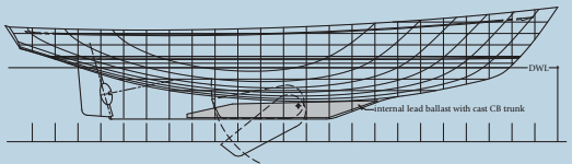
Consider fin keels in two distinct types: internally ballasted and externally ballasted. With internal ballast, the keel is a monocoque part of the hull and the ballast is inserted into the “keel envelope.” This has some problems. If you are building a boat in a one-piece mold, the keel shape will have to be such that it can be pulled out of the mold. But the mold itself is more likely to be in two pieces joined on the centerline for the hull
lamination process. With a one-piece mold, the foil distribution of the fin will be restricted. The keel must be wider at the root than it is at the tip or it will get stuck in the mold.
Even with a two-piece mold, the designer has to take into consideration that humans are going to lay up the boat. As the keel tapers toward the trailing edge, it becomes difficult to get your hands down into the keel to laminate. Any kind of bulb-type shape near the tip will also increase the ergonomic challenge. Pragmatic construction considerations can play a big part in the design of the keel. You often hear the term “encapsulated keel” or “encapsulated ballast.” I would assume this means internal ballast glassed or capped in place with glass-reinforced plastic (GRP).
Placement of the keel
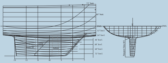
The longitudinal center of gravity (LCG) of the ballast inside the keel must offset the center of gravity of the rest of the boat so the boat floats on its lines. The LCG of the boat without the ballast is usually well aft, so the LCG of the ballast has to be forward in order to get the total center of gravity in fore-and-aft alignment with the boat’s center of buoyancy.
So, for trim, the ballast generally wants to be forward. But to balance the forces on the rig, especially when the boat is hard-pressed and heeled over, the keel needs to be well aft. This is a conflict faced in almost all sailboat designs.
The solution is a long fin where the ballast will occupy only the forward portion of the fin. The designer can also design the ballast slug to have a sloping top so the ballast is much higher forward, pulling the LCG forward. In many cases, moving the ballast slug forward in the fin means there will be a void in the keel aft of the ballast. I like to fill that void with foam and then glass over it to limit the depth of the keel sump. It’s just not practical to have a deep and narrow keel sump. It’s hard to reach down there and retrieve your wrench. Internal ballast requires that the designer choose a foil thickness that allows for a thick GRP keel skin and a reasonable working tolerance in order to slide the ballast slug down into the keel envelope. This additional thickness will increase the frontal area of the fin and that’s not good. With careful manipulation of the keel planform, foil thickness, foil choice, and the ballast-slug configuration, the designer can design a suitable internally ballasted keel.
All but one of the boats I designed that were built in Taiwan, starting in the mid 1970s, were single-piece hulls laid up by hand in two-piece molds with internally fitted ballast. Most used cast-iron ballast with the ballast going in as a one-piece slug. Cast iron was cheaper than lead. Internal ballast meant the builder did not have to bolt the keel onto the hull. I have heard the stories about BBs in the keel and other weird substitutions for a single iron slug, but I’ve never see it. The Taiwan builders and marketers liked internal ballast because it removed all the concerns that come with having to bolt the keel onto the hull.
Robert Perry is the principal of Robert H. Perry Yacht Designers in Seattle, Washington. In a career spanning nearly 40 years, he has designed a wide variety of sailboats, many of which now fall into the category of “sought- after good old boat.”
In the next issue, in “All about keels, Part 2,” Bob Perry will continue this discussion with a focus on keel shapes.
Thank you to Sailrite Enterprises, Inc., for providing free access to back issues of Good Old Boat through intellectual property rights. Sailrite.com