How it can come unhinged under stress
Issue 112: Jan/Feb 2017
Cliff Moore has had his share of trouble with transom-hung rudders (see “Rudders I Have Loved and Lost,” January 2017). In my article “How Sailboat Rudders Evolved,” in the January 2015 issue, I touched on almost every rudder configuration except the transom-hung rudder. I’ll now rectify that omission.
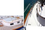
The primary advantage of a transom-hung rudder is that it can be more easily removed without having to haul the boat. Mounting the rudder on the transom also greatly simplifies the structural requirements of the rudder stock, stock seal, bearings, and tiller head. The vast majority of transom-hung rudders are tiller-steered because of the challenge of mounting a quadrant through the transom. For this and other reasons, transom-mounted rudders tend to be used most often on boats well under 30 feet in length.
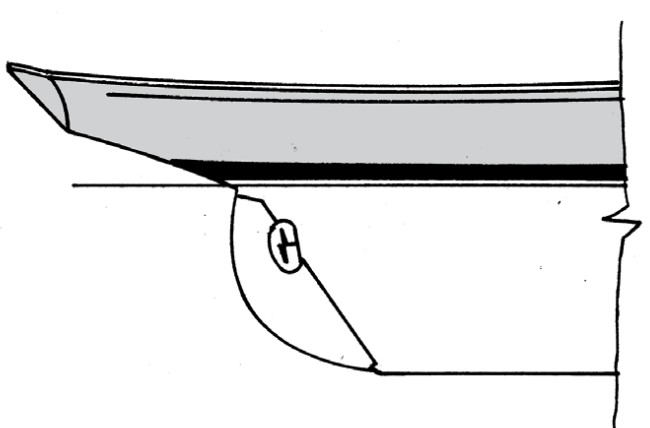
At one time, all rudders were mounted with pintles and gudgeons — USS Constitution, Cutty Sark, HMS Bounty. Even on yachts, well up to the 1950s, rudders were traditionally hung by pintles and gudgeons to the deadwood that formed the full-length keel of most boats (see the illustration above). In this configuration, the load on the rudder was uniformly supported by the massive structure of the deadwood. The only real load on the rudder was torsional, imposed by the tiller or the wheel.
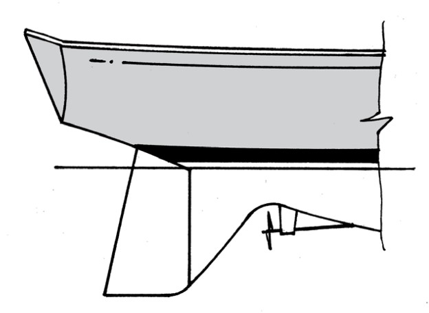
The way rudders have to cope with loads has changed since designers started to cut away the deadwood to reduce wetted surface aft, leaving the rudder to operate independently of the deadwood. Some skeg installations maintain full support of the rudder over its length (see the illustration above), although a lot of skegs are not structural.
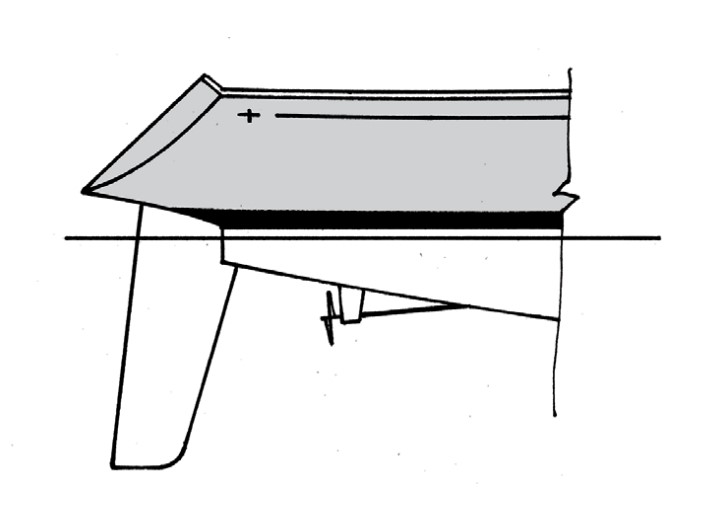
This process led ultimately to the fully cantilevered spade rudder that has now become pretty well the norm in modern yacht construction (see the illustration above). In this configuration the entire load of the rudder is absorbed by the stock in bending at the point it exits the hull.
A confluence of weaknesses
On a free-standing transom-hung rudder, the bending moment must be supported by the rudder itself at the point of the lowest support, the lower pintle. For a fiberglass rudder, that means the fiberglass shell of the rudder must be strong enough to support that bending moment at the location of the lower pintle.
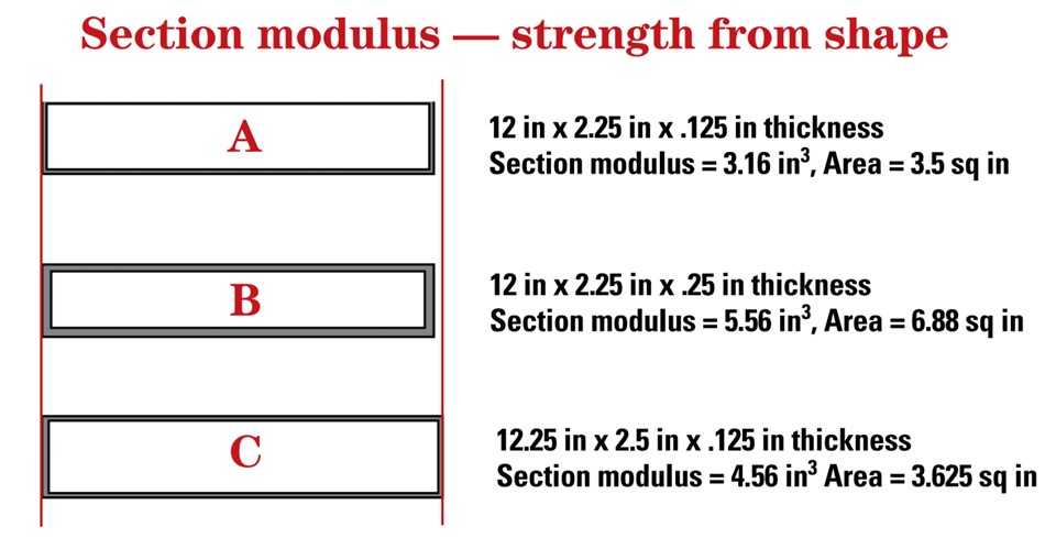
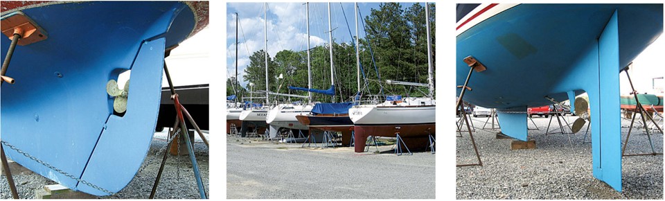
The upper part of the PY26 rudder where the pintles are attached is a box section of fiberglass over a foam core. The resistance of such a structure to bending loads is calculated using the strength of the material, in this case fiberglass, and the section modulus of the area of material. (See “Section Modulus,” above). The integrity of the foam core is crucial to maintaining the box shape.
The foam core is fine for the first few years of a boat’s life, if no water ever enters the rudder. But water will always enter the rudder — through the fasteners for the pintles and thence by gravity into the core, through the leading- and trailing-edge bond lines of the rudder, or through grounding damage. Once this water is absorbed into the low-density urethane foam and is exposed to a few wintertime freeze-thaw cycles, the core starts to break down and lose its properties.
Cliff’s rudder could potentially generate 990 pounds of lift (see “Calculating Rudder Loads,” below). If the foil-shaped rudder blade had simply faired into a rectangular shape at or near the waterline (some distance below the lower pintle), the full width of the blade and its thickness, (2.25 inches), combined with adequate laminate thickness, should have had sufficient section modulus to withstand the bending load. However, the need to balance the torsional loads on the rudder by placing as much as 12 percent of the rudder’s immersed area in front of the turning axis (the pintle pins) enters the picture. (That 990-pound lift acting at a point 25 percent along the chord of the rudder would produce a load at the end of a 36-inch tiller of more than 100 pounds!) By adding a 12 percent balance to the rudder, that tiller load is essentially cut in half.
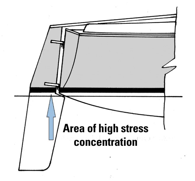
On a transom-hung rudder, that balance area has to extend forward of the lower transom corner, which creates an offset in the leading edge of the rudder and reduces the cross sectional area and, critically, section modulus, right in the area of the lower pintle, which is also the location of maximum bending moment.
With all these challenges facing the design of a transom-hung rudder what could possibly make it worse? Let’s look at the core in this critical area below the lower pintle. The outer skins in this transition area are extremely highly loaded in tension on one side and in compression on the other. All that separates these load-carrying surfaces is the core material. This core, trapped between the area of maximum tension on one side of the rudder and maximum compression on the other, is supporting very high shear loads. At the same time, the skins on the compression side want to buckle under that high loading and the only thing preventing that is the core that is adhered to this skin.
So, even when everything is in good shape and the core has not degraded, you are asking an awful lot of the rudder in this very highly loaded area. On top of all that, drill two fastener holes for the pintle right in the middle of this area, and you really do have a “tear along dotted line” scenario for a rudder failure, as Cliff found out.
Shear on pintles
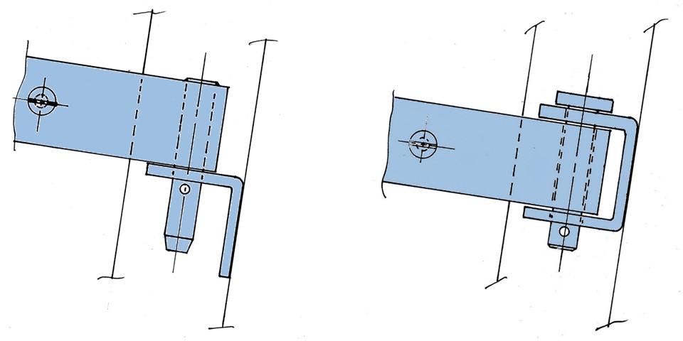
Another breakage Cliff described was due to shear failure of the pintle pins. As Cliff noted, the advantage of a transom-hung rudder is the ability to lift it vertically upward to remove the rudder from the transom-mounted gudgeons. In this arrangement, the entire bending load on the rudder is now supported by that one pin in single shear (see the illustration above left). The shear load on that pin for 990 pounds of lift is about 2,475 pounds. A 1/2-inch diameter stainless-steel pin should take that with no problem, but is very susceptible should there be stress concentration, bad welding, or corrosion in that very defined area of shear.
Also, if the upper pintle makes contact with its gudgeon before the lower pintle makes contact with its gudeon, the lower pintle pin can be subjected to a bending load in addition to the high shear load. A much better solution is to put that pin in double shear, just like a rigging pin, which not only halves the shear load on the pin, but eliminates any welding and most machining (see the illustration above right). This can be achieved with interlocking gudgeons with either separate pins or a single long pin that passes through the upper and lower gudgeons and can be removed by pulling it upward to remove the rudder. This is by far the best solution for mounting transom-hung rudders on boats of any size.

Scaling up
To see the effect boat size has on rudder loads, let’s look at the same rudder configuration as described above on a boat with a 25-foot waterline, an 11 percent increase in size. Following the Law of Scales, rudder area increases by 11 percent squared (23 percent) to 5.54 square feet. Speed, due to greater waterline length, would increase to 14.4 feet per second, and the resulting lift would be 1,360 pounds. The moment, therefore, increases to 3,060 foot pounds. So, an 11 percent increase in size generates a 37 percent increase in lift and a 53 percent increase in bending moment. This is one reason that transom-hung rudders tend not to make the transition to larger boats.
Although a transom-hung rudder appears pretty simple in principle, as Cliff’s adventures illustrate, it presents design challenges that can lead to dramatic and sudden failure. The areas to watch most closely are the highly loaded area below that lower pintle as well as the shear and bending loads on the pintle pins. The rudder should be inspected for stress cracks or crazing and the pintle for signs of bending or corrosion. Both potential failure points should be improved if necessary.
Calculating rudder loads
The load imposed on a rudder is derived entirely from the lift the rudder generates when it is turned to present an angle of attack to the flow. For any given angle of attack, the lift is determined by the simple equation:
Lift = K x (D x A x V2)/2 pounds
K is the lift coefficient
D is the density of water in pounds per cubic foot
A is the area of the rudder in square feet
V is boat speed through the water in feet per second
As the rudder is turned, its angle of attack increases, and in so doing it generates lift.
The lift coefficient, therefore, increases with the rotation of the rudder. The values are well documented for low-speed aerodynamics and low-aspect-ratio foils.
When designing a rudder system, we are interested only in the maximum lift generated, as that is the maximum load the rudder will experience short of a high-speed grounding. Consequently, we are interested only in the maximum lift coefficient achieved. When the fixed values (D and the denominator 2) are combined with the maximum lift coefficient, we get a constant of 1.19 for our rudder design formula:
Lift = 1.19 x A x V2 pounds
The lift coefficient is zero when the rudder is parallel to the flow and at its maximum at full rudder angle, just before the rudder suffers from flow separation and stalls. From this equation, it’s clear that doubling the area of the rudder doubles the lift for a given speed and rudder angle.
Lift on a rudder will, quite clearly, increase with boat speed, but the increase is not linear. Because V in the formula is squared, doubling the speed, say from 3 knots to 6 knots, does not merely double the lift for a given area and angle of attack, it increases it by a factor of 4.
This brings us to the question of what speed to use to calculate the maximum load on a rudder. For that, we look at the boat’s theoretical maximum hull speed, which is related to its waterline length, using the formula:
Vmax = 1.34 x √LWL knots
where 1.34 is the speed/length (V/L) ratio commonly used for most good old boats. However, we all know instances of hull speed being exceeded when surfing down waves. Experience shows a V/L ratio of 1.7 results in a reasonable maximum speed to use in the rudder-load calculation.
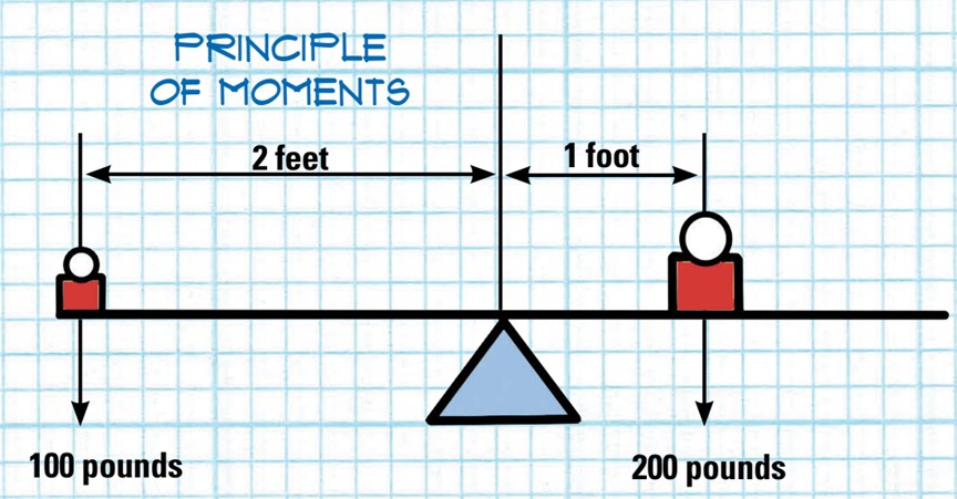
200 pounds placed on the beam 1 foot from the fulcrum creates a moment at the fulcrum of 200 x 1 = 200 foot pounds
The moments are equal and on opposite sides of the beam: the beam stays level.
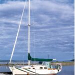
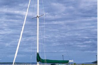
The Paceship 26 rudder
Cliff’s Paceship 26 has a waterline length of 22.5 feet. The maximum speed to use in the lift calculation would be:
1.7 x √22.5 = 8.1 knots = 13.6 feet per second
Absent specific dimensions, assuming the area of Cliff’s rudder is 4.5 square feet, the maximum lift on this rudder would be:
1.19 x 4.5 x (13.6)2 = 990 pounds.
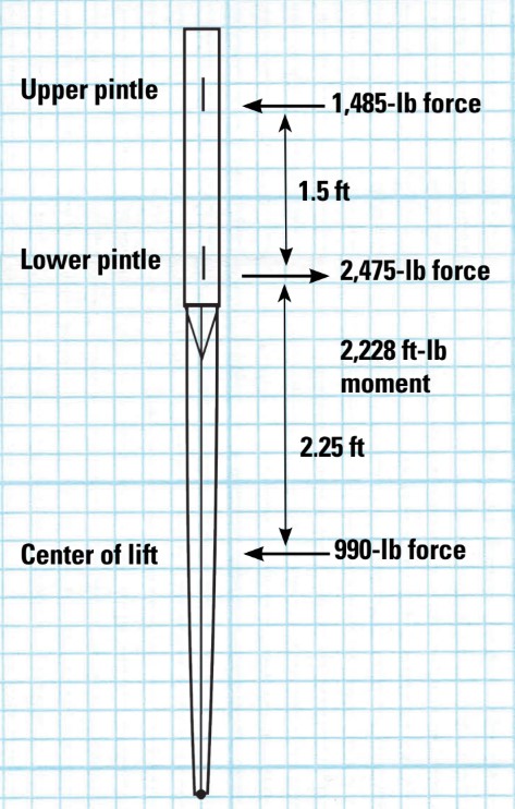
That is, the Paceship 26 rudder is capable of generating almost 1,000 pounds of lift. The rudder’s structure, and its hangings, should be capable of bearing that load.
With the freestanding rudder, like that on the PY 26 or a cantilevered spade rudder, this load translates into a bending moment at the lowest support point of the rudder and a moment arm that extends down to the center of loading of the rudder blade, which is about halfway down the depth of the rudder. If on the PY26 rudder that distance is 2 foot 3 inches, the bending load is 2,228 foot-pounds (990 pounds x 2.25 feet). The shear force on the lower pintle is 2,475 pounds.
Rob Mazza, a contributing editor at Good Old Boat had a long career designing sailboats and engineering their structures and associated appendages. The rudder design parameters at C&C Design were developed from research studies Rob made on low-aspect-ratio foils.
Thank you to Sailrite Enterprises, Inc., for providing free access to back issues of Good Old Boat through intellectual property rights. Sailrite.com