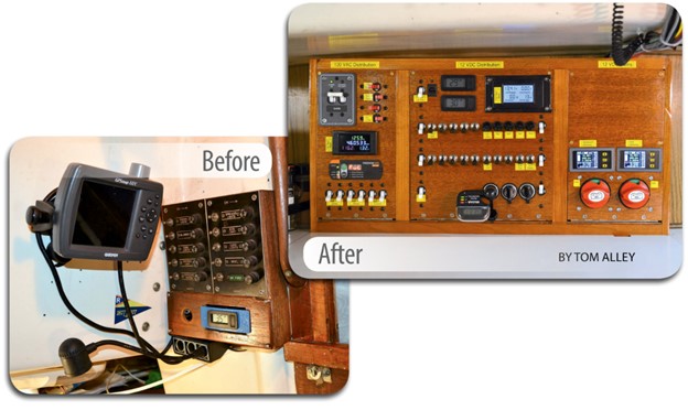
A new alternator delivers on the promise of faster charging
Issue 116: Sept/Oct 2017
Electrical systems aboard cruising sailboats hang by two threads: the capacity and reliability of the batteries and the capacity and reliability of the alternator that charges them. Very often, alternators delivered as original equipment do not have the generating capacity to maintain the batteries at a sufficiently high charge when the boat is in normal use, so many owners choose to install a larger alternator.
Selecting the right alternator for a good old boat involves several considerations. For a couple of reasons, a bigger alternator is usually better. First, most battery types are happier with a large charge current. AGM batteries, for example, resist sulfation longer if the bulk charge rate is between .2 x C and 5 x C, where C is the rated capacity in amp-hours. Using this formula, the 600-amp-hour AGM house batteries on Nine of Cups, our Liberty 458, will be happiest if the alternator can provide at least 120 amps and as much as 3,000 amps! A rather large alternator is required to meet even the minimum output that the battery’s manufacturer recommends.
The second reason a large alternator is desirable is to reduce wear on the engine. We racked up the majority of the hours on our engine charging our batteries. Running a diesel engine with a light load for extended periods is hard on the engine and leads to carbon buildup. We replaced our engine in New Zealand a few years ago and were amazed at how occluded the exhaust manifold had become. A larger alternator puts a bigger load on the engine, making it work harder — which in turn produces less carbon buildup. Thus, when we bought Nine of Cups in 2000, one of the first upgrades we made was to replace the original 80-amp alternator with the biggest and best alternator we could find (and afford). This turned out to be a 200-amp PowerTap alternator.
One of the first things we discovered, however, is that a 200-amp alternator doesn’t really charge the batteries at 200 amps. The reason for this has to do with both how alternators work and how their manfacturers measure their rated output.

First, an alternator’s output increases with its speed — the faster it spins, the more amps it produces. Therefore, many 200-amp alternators will only generate those 200 amps at maximum rpm. Since we usually run our engine at 1,500 rpm to charge the batteries (about half of our engine’s maximum rpm), the actual charge current produced by our alternator is much less than its rated output. Our PowerTap alternator typically generates around 150 to160 amps at this speed.
Second, there is a large difference between the Hot and Cold ratings of an alternator. This is due primarily to the resistance of copper wire, which increases with temperature. When an alternator is at ambient temperature and all its copper windings are cool (Cold), its output is substantially higher than when they are at normal operating temperature (Hot). Not all manufacturers provide specifications based on output at normal operating temperature, so it’s important to bear this in mind when comparing alternators.
The new Balmar alternator
When I was talking alternators with Jerry Powlas, Good Old Boat’s recently retired technical editor, he suggested I take a look at a new high-output alternator made by Balmar. Supposedly, the Balmar AT-Series alternators produce far greater outputs than other comparably sized alternators, especially at low rpm.
I looked at the Balmar specs and was immediately skeptical. Balmar claims that its alternators show a 30 percent improvement over not only its own older designs but its competitors’ designs also. Alternators are becoming more efficient with each decade, but it’s been a slow evolution. Manufacturing and design improvements have eked out small increases in efficiency, but a 30 percent increase seemed unreasonable. I set out to learn more.
It turns out that Balmar did figure out a way to improve its alternators significantly. The efficiency of an alternator is directly related to the density of the copper in the stator winding. To wind the stators of its new alternators, Balmar used wire with a square cross-section (in place of conventional wire with a round cross-section). This change virtually eliminates air gaps between the loops of wire, increasing the overall density of the copper in the stator winding. Additionally, Balmar increased the number of slots in the stator from 36 in a traditional S-wound alternator to 96 in its new AT stator. The Balmar website provides several graphs that show the improved performance that results from these changes; I was definitely intrigued. When Balmar offered me the use of one of their new alternators for testing, I was happy to oblige.
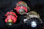
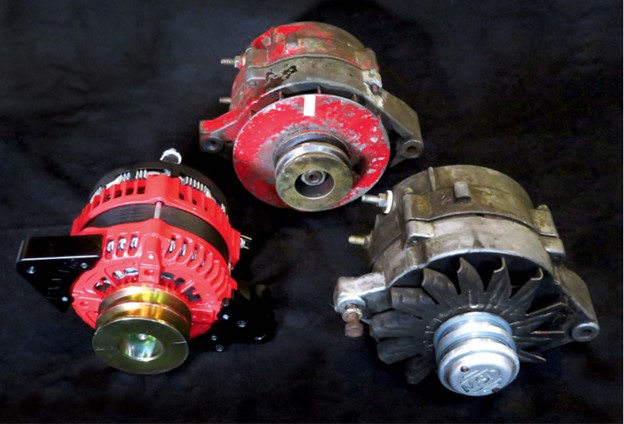
The company sent me a new Balmar AT-SF-200 alternator. It has a bright-red powder-coated finish and appears well built and designed for the marine environment. This model comes in several mounting configurations to match different engines, and I chose the model with the same foot and mounting dimensions as my current PowerTap and my backup 80-amp alternator, making the mechanical installation easy. I also chose a double- belt pulley option to match my existing arrangement.
I met only a couple of minor incompatibilities. My alternators use a different field/tach connector than the Balmar, so I fabricated a pigtail arrangement with both types of connector in parallel. Another minor issue was that both my old alternators use 5 /16-inch studs for the positive and negative terminal connections, while the Balmar provides an 8mm stud for the positive terminal and a 6mm stud for the negative terminal. I’m sure this is to reduce the likelihood of reversing the cables, but it means that I would be faced with a dilemma if I were to keep the alternator: Should I change the terminal on the negative cable to fit the Balmar, making it too small for my backup alternator, or use the existing, slightly oversized terminal with the Balmar, increasing the resistance of the connection? I think I would take the first approach, knowing I would have to jury-rig a high-current jumper if ever I had to use my backup alternator.
Test equipment
My plan was to measure the outputs of three alternators at various rpm: my original 80-amp Motorola alternator, my 200-amp PowerTap alternator, and the new Balmar 200-amp alternator on loan for me to test. Before I could do any testing, however, I needed some new test equipment.
Before sailing off on Nine of Cups, I’d worked as an electrical engineer in an industry in which it was often necessary to take highly accurate measurements. Measuring to these degrees requires expensive calibrated equipment that was well beyond my budget. The equipment I could afford to buy would not yield results that were traceable to the National Bureau of Standards, but I did perform several crude calibration and accuracy checks to determine whether the results could be trusted. More on this later.
My test equipment consisted of the following:
- Current measurement: Craftsman 82014 digital multimeter with DC-current clamp
- Voltage measurement: Topone 820B digital multimeter
- Temperature measurement: General Tools IRT207 infrared thermometer
- Speed measurement: AGPtek DT-2234C+ digital laser Tachometer
In addition, I needed a resistive load capable of handling more than 200 amps of current while generating a voltage drop of 12 to 14 volts. Moreover, I needed to be able to vary the load, so that I could maintain the 12- to 14-volt drop over the load as the alternator current increased from a few amps to more than 200 amps.
Doing the math, I determined the resistance would have to vary between .05 and .5 ohms and be able to dissipate 3,000 to 4,000 watts. I did some checking online and found several candidates, but all came with a very high price tag: several hundred dollars to several thousand dollars.
I thought I might be able to use electric space heaters, but after measuring the resistance of one, I came to the conclusion that I would need 200 heaters in parallel to get the resistance low enough! I could find no inexpensive solution other than to build a fixture myself.
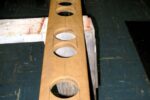
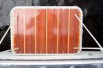
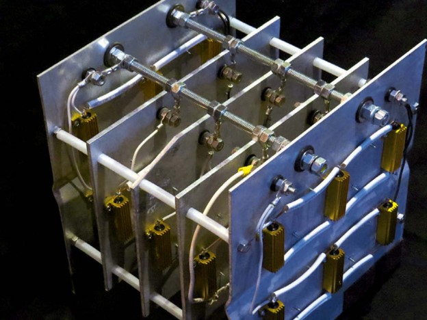
I used 40 2.0-ohm 100-watt 1 percent resistors mounted on several large sections of scrap aluminum sheet metal. Any or all of the resistors could be connected to the circuit using jumpers. It took me two days to build the fixture at a total cost of about $100.
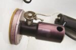
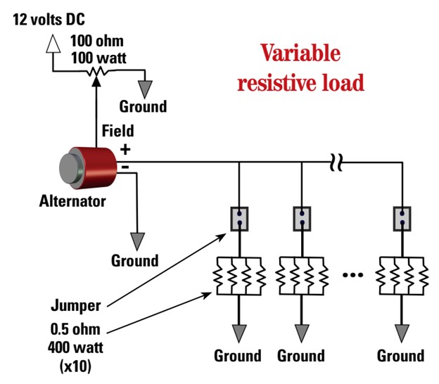
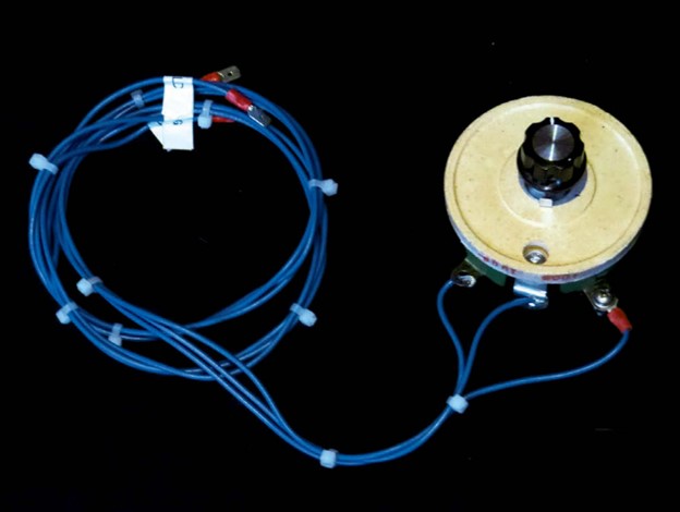
To control the output of the alternators, I connected the field wire to 12 volts DC via a 100-ohm 100-watt potentiometer. By rotating the pot, I could modify the field current from zero to fully on. (See the schematic on page 19 for details of the test circuit.)
Test protocol
I mounted each alternator on my engine in turn and, for each one, measured the current generated while I increased the engine speed from idle (600 rpm) to 80 percent of full throttle (2,200 rpm). As the engine speed increased, I decreased the resistance of the load to keep the alternator voltage between 12 and 14 volts DC.
The ratio of the engine pulley to the alternator pulleys is 2.4:1, which means the alternator speeds ranged between 1,450 and 5,300 rpm. Through this range, I took measurements at eight different speeds, increasing the speed roughly 500 rpm between data points. At each data point, I measured the alternator frame temperature, alternator speed, alternator current, voltage across the resistive load, and the temperature of the resistive load.
I allowed each alternator to reach an operating temperature of between 190°F and 245°F. I tested the PowerTap alternator first, followed by the 80-amp Motorola alternator and then the Balmar. I repeated the test using the PowerTap alternator to verify that the results were consistent.
Results
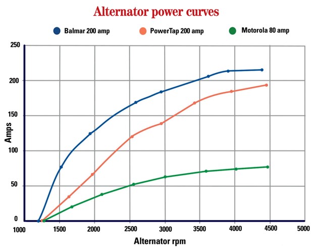
The graph on the facing page shows the test results for the three alternators. The results for the two older alternators did not surprise me — they were very much in keeping with the charge currents I was experiencing. The results for the Balmar were slightly better than the results I was expecting, based on the data given on the Balmar website. What is most interesting is the low-rpm performance of the Balmar alternator. It ramps up much more quickly than the PowerTap, which is an important consideration in an application like ours on Nine of Cups.
As noted above, the pulley ratio for Nine of Cups’ alternator is 2.4:1. The table on the facing page compares the outputs of the three alternators based on engine speed rather than alternator speed. At an engine speed of 833 rpm — barely above idle — the Balmar alternator produces 126 amps. This is 80 percent better than the PowerTap! The Balmar also reaches a very respectable 184 amps at only 1,250 rpm, 30 percent better than the PowerTap at the same speed. I was impressed.
The table also shows the calculated load on the engine in horsepower at the various engine speeds. As expected, the Balmar alternator loads the engine more at lower rpm than the others. This loading makes the engine work harder, reducing the amount of carbon buildup for those of us who frequently use an engine to charge the battery bank.
My conclusion is that the Balmar AT-Series alternators are everything Balmar claims them to be, and anyone thinking of upgrading their charging system should definitely consider them.

Caveats
As mentioned earlier, my test equipment and environment were less than ideal. In a perfect world with an unlimited budget, I would have had my test equipment calibrated by an independent lab, I would have done the testing in an environmentally controlled workspace, the alternators would be driven by digitally controlled motors, and the resistive load would be computer-controlled. This is not quite how I was able to do my on-site testing on Nine of Cups.
Where possible, however, I did cross- check my instrumentation with other equipment, I took several readings to check consistency, and I repeated individual measurements. I conducted all of the testing within a few hours, so the ambient conditions were similar, and I ran all three alternators long enough under load to reach operating temperature. The Motorola and PowerTap alternators ran slightly cooler, between 190°F and 225°F, while the temperature of the Balmar alternator was warmer, between 210°F and 245°F.
In addition, I tested the PowerTap alternator twice, once at the beginning of the testing process and again at the end, to check the repeatability of the testing. I found it impossible, using the throttle on Nine of Cups, to set the engine to the exact same speed for all data points, so I did a linear interpolation of the data in order to compare results. Assuming my assumptions were reasonable and my calculations were correct, the results compared favorably, within plus or minus 4 percent.
Thus, I feel reasonably confident that, while the testing may not be up to laboratory standards for absolute accuracy, I achieved an acceptably accurate comparison of each alternator to the others.
David Lynn is Good Old Boat’s electronics editor. He was an electronics technician in the U.S. Navy for six years before getting his BS and MS in electrical engineering. He spent his career designing electronic instrumentation utilizing embedded microcontrollers. David and his wife, Marcie, sold all their land anchors and have been living aboard Nine of Cups, their 1986 Liberty 458 cutter, since purchasing her in Kemah, Texas, in 2000. In those 17 years, they have sailed her nearly 90,000 nautical miles and visited some of the more remote places in the world in their ever-so- slow world circumnavigation. Nine of Cups and crew returned to U.S. waters last year and are currently cruising Chesapeake Bay and converting a van into a land cruiser. Find them on their website at www.nineofcups.com or their blogsite at www.justalittlefurther.com.
Thank you to Sailrite Enterprises, Inc., for providing free access to back issues of Good Old Boat through intellectual property rights. Sailrite.com