One boat’s discard is another’s chill deal
Issue 122: Sept/Oct 2018
One day at the dock, my slip neighbor James asked me if I had a need for a refrigeration unit on my 1965 Alberg 35. “I had to replace mine last year,” he said. “My dad fiddled around with it, found a leak, and got it working again, but I wouldn’t feel right selling it to someone and then having it stop working six months later.”
As I was still lugging ice to keep the beer cold, I didn’t see how I could refuse, and found myself in possession of an Adler/Barbour refrigeration unit that once lived in a Tartan 31. The labels on it were not readable, but after some searching on the internet I was able to download a couple of manuals that looked to be appropriate to the model.
Testing before investing
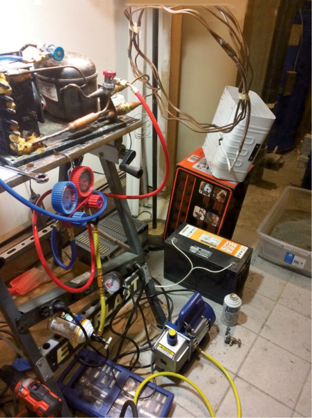
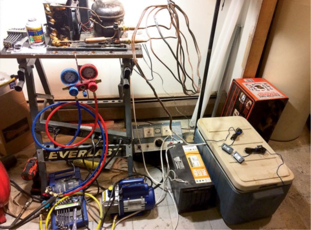
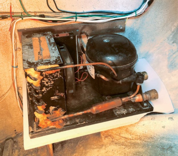
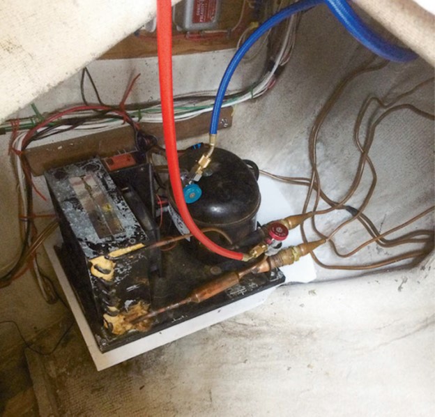
Before installing it, I wanted to make sure that the unit would function long enough to warrant the effort, so I set myself up in my basement to test it. Initial tests went badly. Pressure gauges I connected to the unit showed me there was no refrigerant. After investigating, I discovered that one of the couplings between the compressor and the evaporator was not torqued down sufficiently to create a proper seal.
I first charged the low-pressure side of the refrigerator with 60 to 70 pounds per square inch (psi) of compressed air and monitored the gauges to see whether the pressure dropped over some period. Three days later, the gauges were still reading the same pressure, so I declared the leak to have been found and fixed. Next, I recharged the unit with refrigerant and ran it for a while on the workbench.
Because the unit had been manufactured in the early 1980s, it had been charged with the now-banned Freon, also known as R-12. For most mobile applications, R-12 has been replaced with R-134a. Unfortunately, the two aren’t simply interchangeable and do not perform the same. To use R-134a, I would have to purge and clean the unit, because the lubricating oil used with R-12 (typically mineral oil) is not compatible with R-134a. Having read several stories about R-134a retrofits ending badly after six months because of compressor problems, I was hesitant to mess around with the compressor lubricants. I also knew I could expect up to a 10 percent reduction in performance from replacing R-12 with R-134a.
A few days later, I came across a product called Maxi-Frig, which is advertised as a drop-in replacement for R-12 refrigerant. The supplier asserts that Maxi-Frig is compatible with all types of compressor oils (mineral, synthetic, ester, and PAG). Further research revealed that the product is a mixture of propane and isobutane (usually referred to as a “hydrocarbon-based” or “HC-based” refrigerant) that mimics the characteristics of R-12. It actually improves the performance of the refrigeration system by about 6 percent and, making it even more attractive, only one-third as much Maxi-Frig 12a is needed to replace a given amount of R-12. Some states ban the use of HC-based refrigerant in automotive applications due to its flammability, but since I have 10 pounds of liquified propane on board for the galley stove and a full gas-detection system in the bilge, I didn’t think a few extra ounces of propane and butane would bring any significant increase in risk. I ordered some Maxi-Frig and compressor oil.
I evacuated the system, bled in some refrigerant, and cycled the compressor a few times to distribute the refrigerant throughout the system. Once I had about half of the refrigerant that I thought I would need, I started up the unit and adjusted the charge to be approximately where I wanted the temperatures to be. (When charging an AC unit, the temperatures attained in the evaporator and compressor are directly related to the refrigerant pressures.) I then added oil to ensure that the compressor was well lubricated.
It wasn’t long before the evaporator started to “sweat” and feel cold to the touch, and it soon had a thin layer of frost on it. A quick look through a thermal camera I borrowed from work confirmed that everything was working as it should.
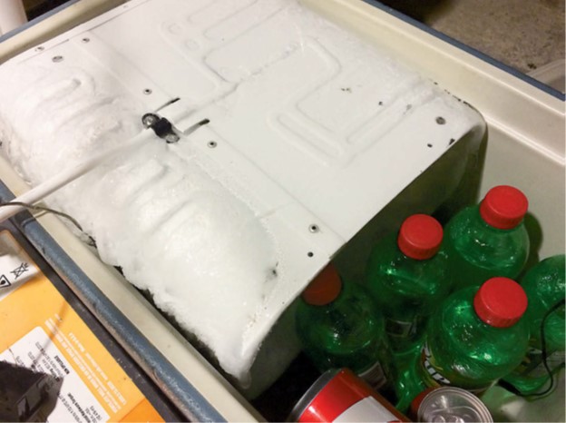
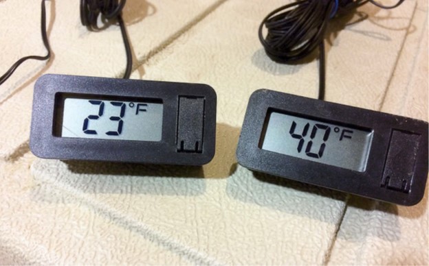
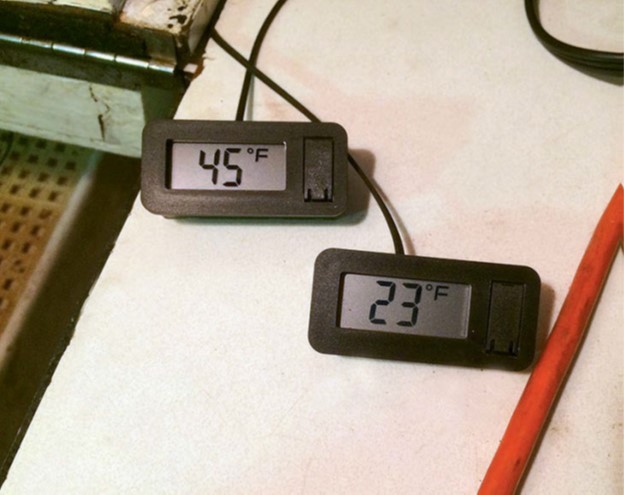
The next step was to simulate “field conditions,” so I loaded a picnic cooler with soda and beer and put the evaporator into it. I had a couple of digital thermometers available and placed one in the “freezer” (the interior of the evaporator) and the other in the “refrigerator” (the section with the beer and soda). After a couple of hours, the temperature gauges showed promising numbers.
Flush with success, I let the system run for about six weeks, occasionally checking the battery charger to make sure I wasn’t over- or under-charging the battery, and also sampling a beer or soda from time to time to ensure it was at the optimal temperature. Because the refrigerant lines prevented me from completely closing the lid to the cooler, the “freezer” did ice up over time, which I took as a favorable sign. By this time, my teenage sailing crew were planning cruising menus that included ice cream.
On to the installation
As my confidence in the system grew, I shifted my focus toward the installation phase of the project, and my first task was to figure out where to locate all the components and how to route the refrigerant lines between them. Because the refrigeration unit is air-cooled, it had to be mounted where it could breathe and shed the heat it pumped from the icebox.
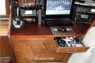
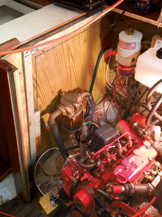
Fortunately, the space under the Alberg 35 cockpit is large enough to satisfy Adler/Barbour’s requirements (about 100 cubic feet). A small shelf already glassed into place at the forward end of the starboard cockpit locker immediately aft of the icebox, and adjacent to the main electrical distribution point in the boat, would allow for straightforward routing of the electrical wiring as well as the refrigerant lines.
The compressor footprint was slightly larger than the shelf, so I cut a piece of 1/2-inch plywood larger than the shelf, sealed it, painted it, and screwed it into place. I then bolted the compressor and condenser to the shelf.
Getting at the icebox posed a challenge. As on most boats, my Alberg 35’s icebox is a built-in component of the interior cabinetry installed before the deck was fitted. I would have to open up at least one bulkhead simply to gain access. An extended trip through the New York Canal system the year before had revealed the engine’s ability to melt ice in the icebox at a fantastic rate, so I also had an incentive to upgrade the insulation however possible.
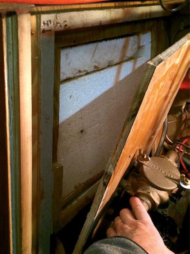
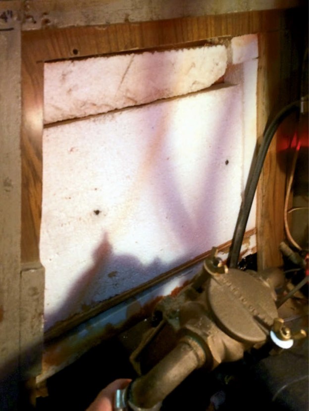
Using an oscillating multi-tool, I cut through the bulkhead between the engine and the icebox. Removing the panel answered most of the questions I had about the icebox design and construction. The icebox itself is made of plywood, and the interior is painted. The insulation was solid 2-inch-thick Styrofoam around the top, sides, and bottom. The piece covering the bottom had fallen off at one end, which probably contributed to the rapid ice melt from engine heat.
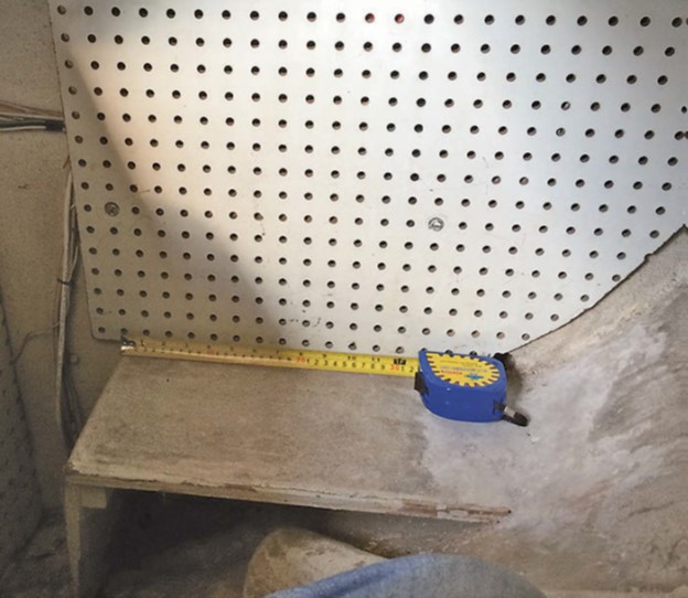
To determine where to locate the evaporator coil, I made detailed measurements of the inside of the icebox. After some deliberation, I decided to locate the evaporator coil near the aft end of the icebox, where it would interfere least with the icebox opening and the upper “shelf” of the icebox itself. I drilled a 1 1/2-inch hole through which to pass the refrigerant line and couplings, and for an additional pair of wires for the future installation of a small circulating fan to help equalize temperatures within the icebox cavity. I used standoffs to create a 1-inch space between the evaporator and the sides of the icebox.
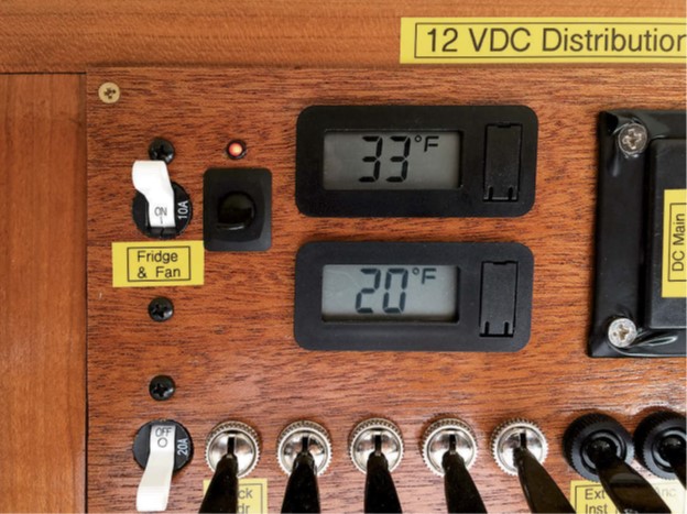
While I was at it, I decided to install a couple of temperature sensors so that I could ensure that future payloads of egg salad remained domesticated while being stored. I placed one sensor inside the evaporator (which I hoped would become the “freezer” section of the box) and the other sensor high in the forward end, where I believed the warmest temperatures might occur. I located the refrigerator thermostat/control here, too, figuring this would provide the most pessimistic reading within the box and therefore help me prevent any food from going bad.
I snaked the refrigerant lines from the icebox to the compressor, connected them, and torqued them to specifications to ensure a good seal. After wiring the compressor into the boat’s DC distribution, I powered the unit on and charged it with refrigerant and oil.
Reassembly and insulation
Because the hole in the side of the icebox was rather large, and condensation in this area was likely, it had to be sealed with something that was moisture-resistant. I cut a piece from the side of a gallon plastic milk jug and glued it into place with TotalBoat Seal. With this arrangement, I can remove the seal should the time come to replace the refrigeration unit.
Before reinstalling any insulation, I powered on the system and allowed it to run overnight, and checked temperatures and pressures to verify that there were no leaks. The temperature gauges showed promising results, and the pressure gauges held steady. This gave me the green light to proceed with rewrapping the box with insulation and putting back the bulkhead between the engine and the icebox.
For the new insulation, I used polystyrene foam panels with aluminized faces to help reflect away heat. These panels, which I obtained from Lowe’s, are rated at R-5, which should slightly improve resistance to heat from the adjacent engine compartment compared to raw Styrofoam, which is rated R-4. I sealed the seams with foil tape, then placed a second layer of panels over the first with the seams in different places.
The drains in the original icebox emptied into the bilge, and also provided an escape route for cold air to leak out. While everything was apart, I rerouted the drain tubing to form a trap where condensate could accumulate and form a seal to minimize further leakage. I then fixed the detached Styrofoam insulation back into place and added insulation beneath the icebox in such a way that it could not fall away from the icebox again.
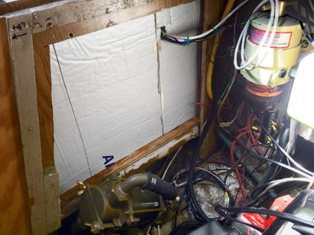
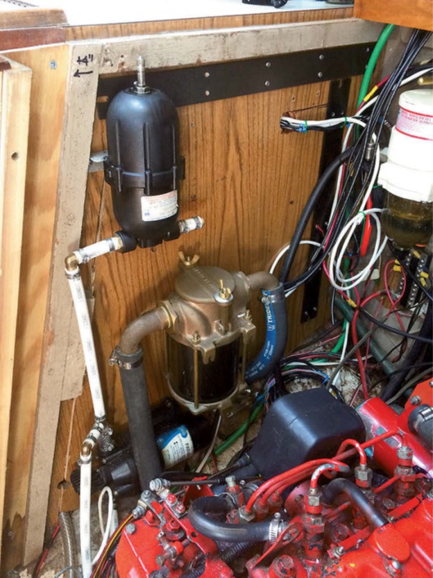
With the insulation work completed, I replaced the bulkhead and secured to it the water strainer for the engine and the pressure water pump and accumulator.
Because of space constraints in the engine compartment, I cut some additional rigid foam panels to fit inside the icebox to increase the insulation thickness to 3 inches on the bottom and the side facing the engine. While this does reduce the volume of the icebox, because I no longer carry ice, there is still a net gain in storage capacity.
The cruise test
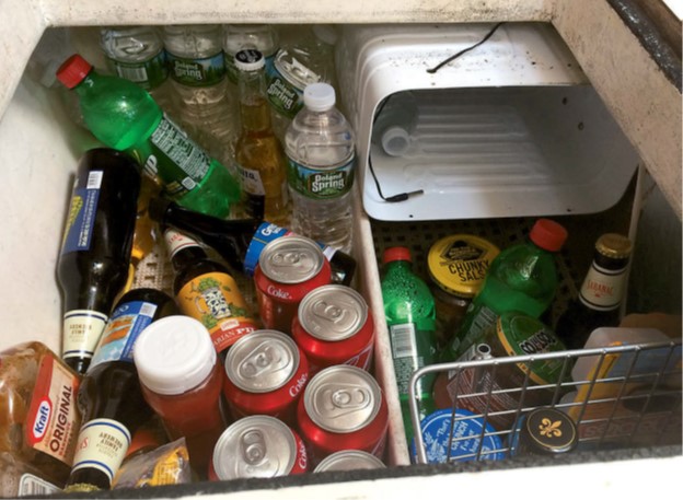
To test the results of all my work, we went on a weeklong cruise. Our crew drew up a menu of meals, wrote up a list of provisions, and set out for the grocery store to pick up some perishable items along with beer and soda. Over the course of the week, we enjoyed a number of cold beverages, and the temperature gauges gave us confidence that none of our food had gone bad. While we were unable to make any ice cubes, that might be possible in the future if I add a door to the “freezer” compartment.
Battery monitors in the boat’s electrical panels showed that the refrigerator draws around 6 amps when running, making it a significant load on the house banks when we are anchored out overnight. Along with other house loads, refrigeration has increased our energy needs to approximately 140 amp-hours per day when we are under way, necessitating a well-functioning alternator on the motor to recharge the batteries daily. Fortunately, Tomfoolery is equipped with two house banks, each with a capacity of 200 amp-hours.
I also noted that we did not hear the compressor cycle very often, so I may need to tweak the refrigerant charge.
Overall, installing refrigeration was well worth the effort and has raised our standard of living aboard Tomfoolery significantly. In the future, I plan to add a small fan to circulate air to keep temperatures a bit more even throughout the icebox.
Tom Alley and his family, sailing their 1965 Alberg 35 sloop, Tomfoolery, are active racers and cruisers with the Finger Lakes Yacht Club in Watkins Glen, New York. Tom has been a member of the US Power Squadrons since the late 1980s, when he got serious about sailing and having fun on the water. He has been a Squadron Education Officer for longer than he cares to remember. He also manages the Alberg 35 User Group website (www.Alberg35.org). When he’s not sailing, tinkering with his boat, scuba diving, or hanging out with fellow amateur radio operators, as a last resort he works as an engineer to support his sailing addiction and, if there’s any money left over, send his kids to college.
Thank you to Sailrite Enterprises, Inc., for providing free access to back issues of Good Old Boat through intellectual property rights. Sailrite.com