An electrical update for the 21st century preserves the 1960s aesthetics.
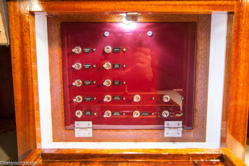
Dog-eared and dated, the 12-volt DC switch panel on our 1961 Alden Challenger, Christmas, was original. I had planned to replace it for some time but other projects took priority until last winter, when I made the time to take it on.
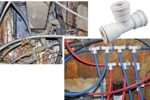
The first step was to cut the old switch panel out of the boat and see what was actually in there. It was interesting to dig into the state of the art of boat electrics circa 1960. The old main unfused cable from the house-battery bank was bolted to a terminal post and fed the toggle switches via a solid uninsulated copper wire. Nearly all the switches soldered to this solid bar were STDP (single throw, double pole), probably to save space.
An STDP switch controls two mind-boggling heaps of wires burying circuits. The throw of the switch turns both circuits on or off, which is handy for devices that have their own switches, like cabin light fixtures.
From the switches, the 1960s electricians split the power, via two ring terminals on each screw, into as many as four circuits per switch. Thus far, the circuits were still not fuse-protected!
Finally, the switched circuits were soldered to glass SFE fuse holders. The fuse-protected wire then connected to a positive terminal strip in the bottom of the box. The boat’s various circuits were connected to the old panel’s positive terminal blocks and a neutral bus bar.
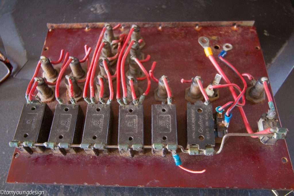
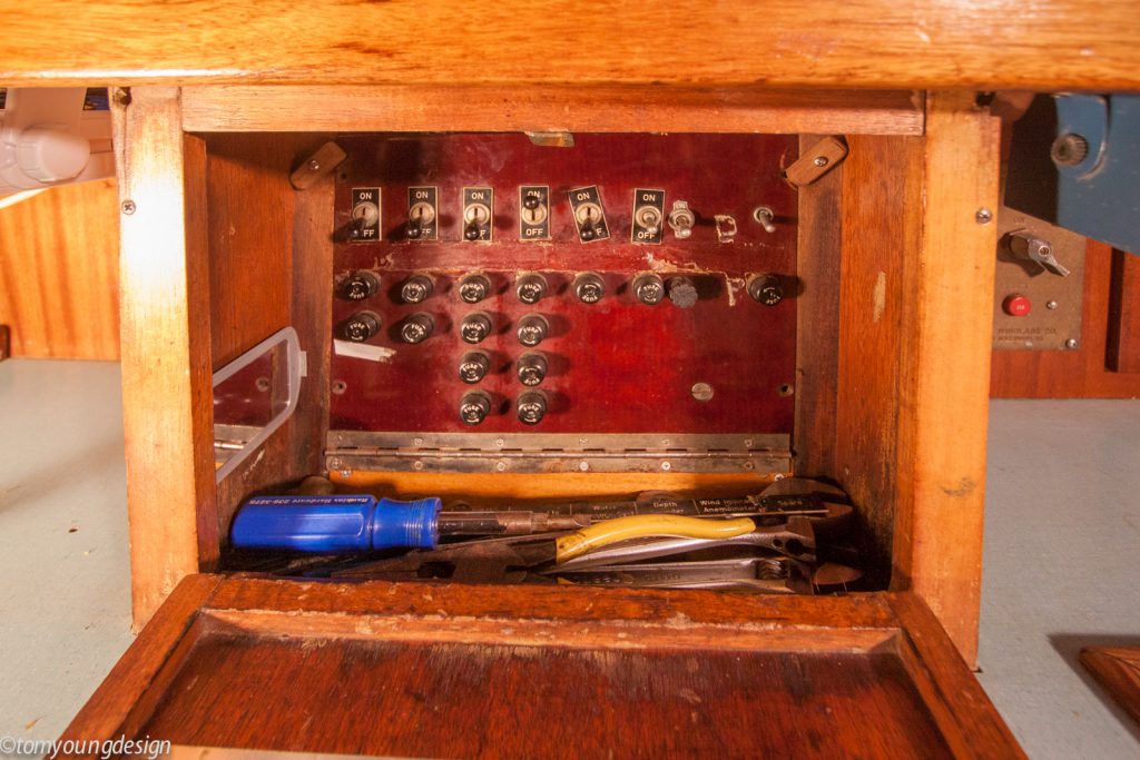
These glaring problems aside — multiple connections on the positive main power post, several inline fuses, mind-boggling heaps of wires burying terminal strips and bus bars, and unfused wires — the old panel still worked. Why change it?
Fire! The vast majority of fires on boats at sea are caused by the 12-volt DC wiring. That was brought close to home when a fiberglass fishing boat caught fire in my harbor, not far from where Christmas was moored.

A loose wire that chafes through, or melts onto a hot engine or exhaust part, will cause a dead short. If that wire isn’t fuse-protected, full current will flow from the battery to the short. The wire will burn white hot along its length, and the result is a fire. I’ve seen this happen on my boat.
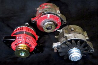
The best additions to an old boat’s electrical system are modern over- current protection devices (OCPDs). In the event of the short circuit described above, a correctly sized OCPD protects the wiring from burning by disconnecting the circuit when it senses more current than the wire can safely carry. Today, we have several types of OCPDs with which to protect all our onboard wiring. That’s a real improvement over 1960 standards.
Design thoughts
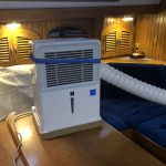
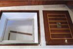
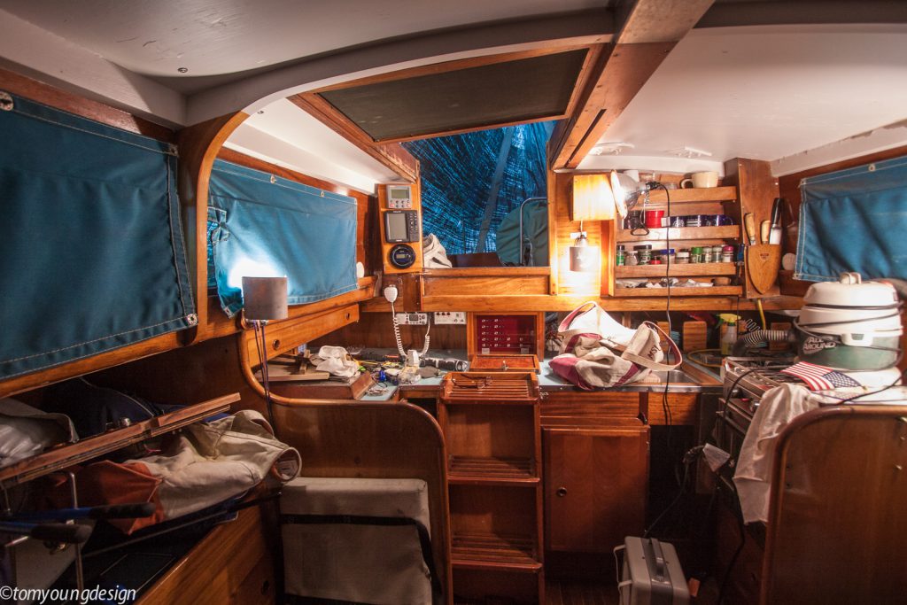
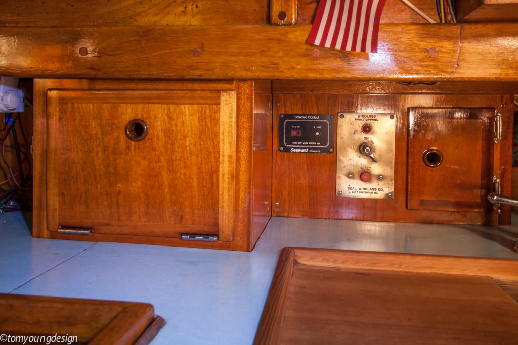
Christmas is a coastal sailer used in season on the coast of New England. A main priority of ours is to have minimal energy requirements to allow us the freedom to sail as much as we want. I enjoy this old boat and try to preserve the 1960s design details that work well. The 12-volt DC electrical panel was installed in a cabinet beneath the companionway, where it was close to the batteries and convenient to use. Tucked beneath the bridge deck and behind a stout door, the panel has stayed dry and protected for 56 years. It’s also a handy place to keep often- needed tools.
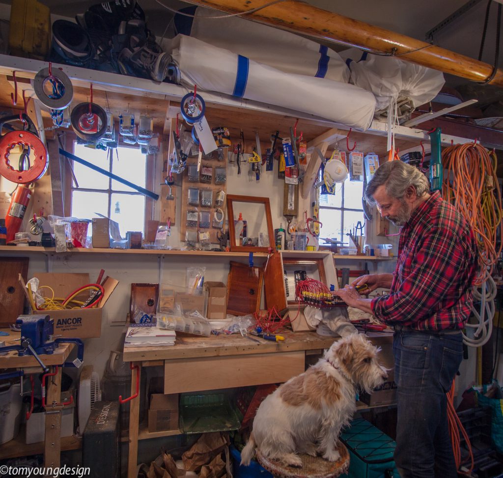
Breaker/switch panels, especially custom made as I would need, are expensive, and no stock panel would fit inside the cabinet. I knew I’d have to design and build my own panel, and I enjoy work like this. The project would be rewarding as well as a money saver. The box was the trick. Performing this tedious work under a dark tarp on the coast of Maine in midwinter wasn’t going to happen. I’d take the work off the boat.
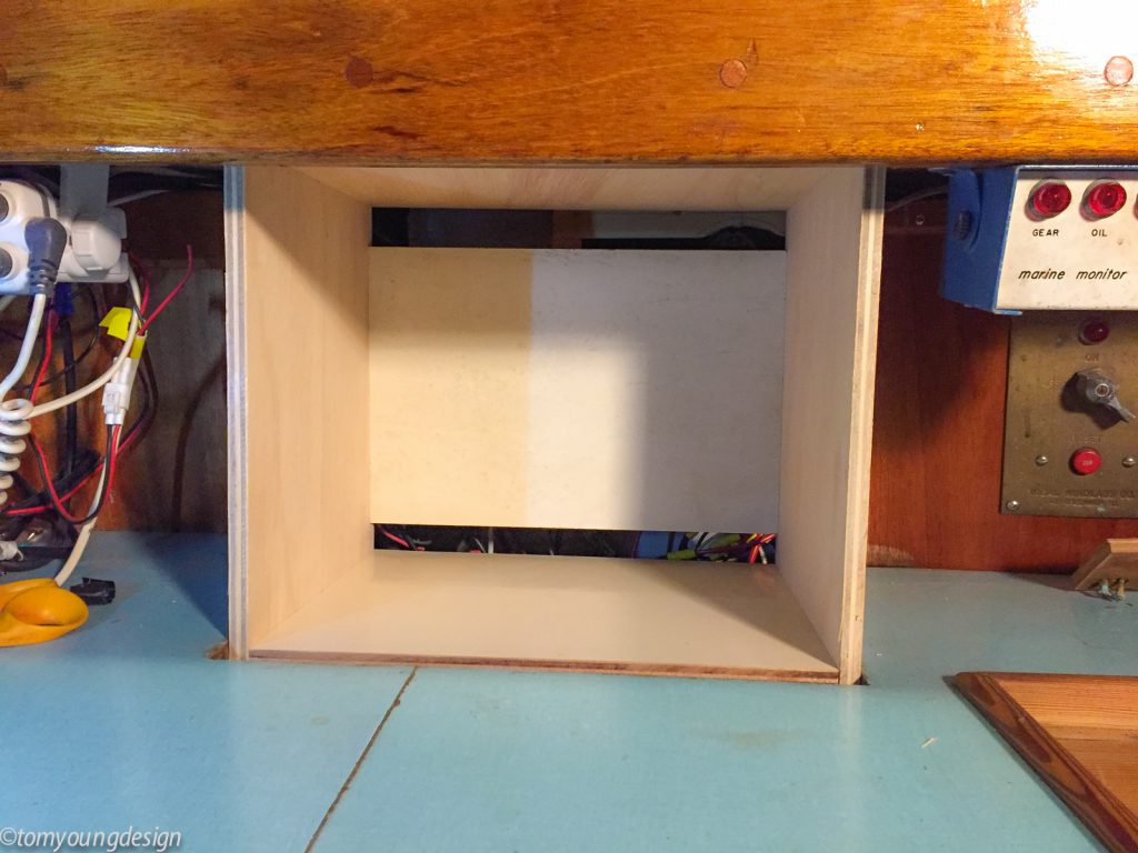
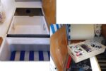
After dismantling the existing cabinetry and taking careful measurements, I built a new plywood 12-volt DC distribution box to fit into the existing space. I salvaged the original nicely built door so I could restore it and fit it to a new frame. Satisfied the box fit the space, I left the tightly wrapped and frigid boat and headed to my warm shop. My plan was to do all the panel wiring comfortably on a bench at my leisure. In the spring, I’d install the completed distribution box on board and move on to connecting the boat’s circuits to the new terminal strips and bus bars.
Our house battery bank has two Group 27 (100 amp-hour) marine lead- acid deep-cycle batteries. A separate engine-starting battery, safely wired and fuse-protected to carry a 250-amp current for the starter load, is isolated from the house battery bank. The house and engine batteries cannot be connected. We have no AC wiring on board Christmas.
This made the general electrical design easy. Using Boatowner’s Illustrated Electrical Handbook by Charlie Wing (a good friend) extensively as a reference, I began researching several sources to determine what parts I needed to build a safe panel. It’s a good thing Maine winters are long because, although studying allowable conductor voltage-drop tables and other details, then gathering up the right parts, was a pleasant process, it took time. The pile of electrical components began to grow on the bench, and it became time to begin installing them all in the new box.
Panel components
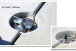
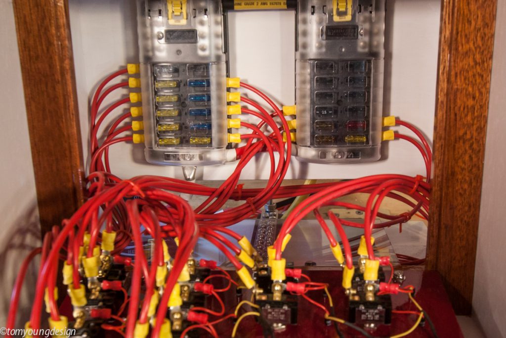
All the components of the electrical system — wiring, switches, fuse blocks, terminal strips, and bus bars — had to be rated to safely carry the current for the OCPDs I chose to use. I decided that ATC fuse blocks — compact, easy to use, and affordable — would work in the limited space. Blue Seas makes several. Their 5026 fuse blocks provide 12 fused circuits. Two of the blocks fit nicely into the open back of the box, yielding a total of 24 fuses, which was comfortably more than I needed. There would be room to expand in the future.
ATC fuses are standard automotive blade fuses and readily available in many sizes, which makes protecting the smallest wires easy. As to fuses vs. breakers, in over 30 years of using boat DC systems with fuses, I’ve likely changed no more than a half dozen. The ATC fuses are far more reliable than the glass variety. They are easy to read, so it’s much less likely an oversized fuse will find its way into a circuit.
When spring came, I would begin work on board, when I would install terminal strips and bus bars to provide more screw terminals for connecting the boat’s circuits.
For the panel itself, I chose to use toggle switches, which were typical in the ’60s. To add a dash of 21st century, I would add LED indicator lights, which I think are intuitive for the switch user.
The switch panel
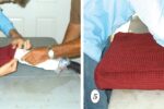
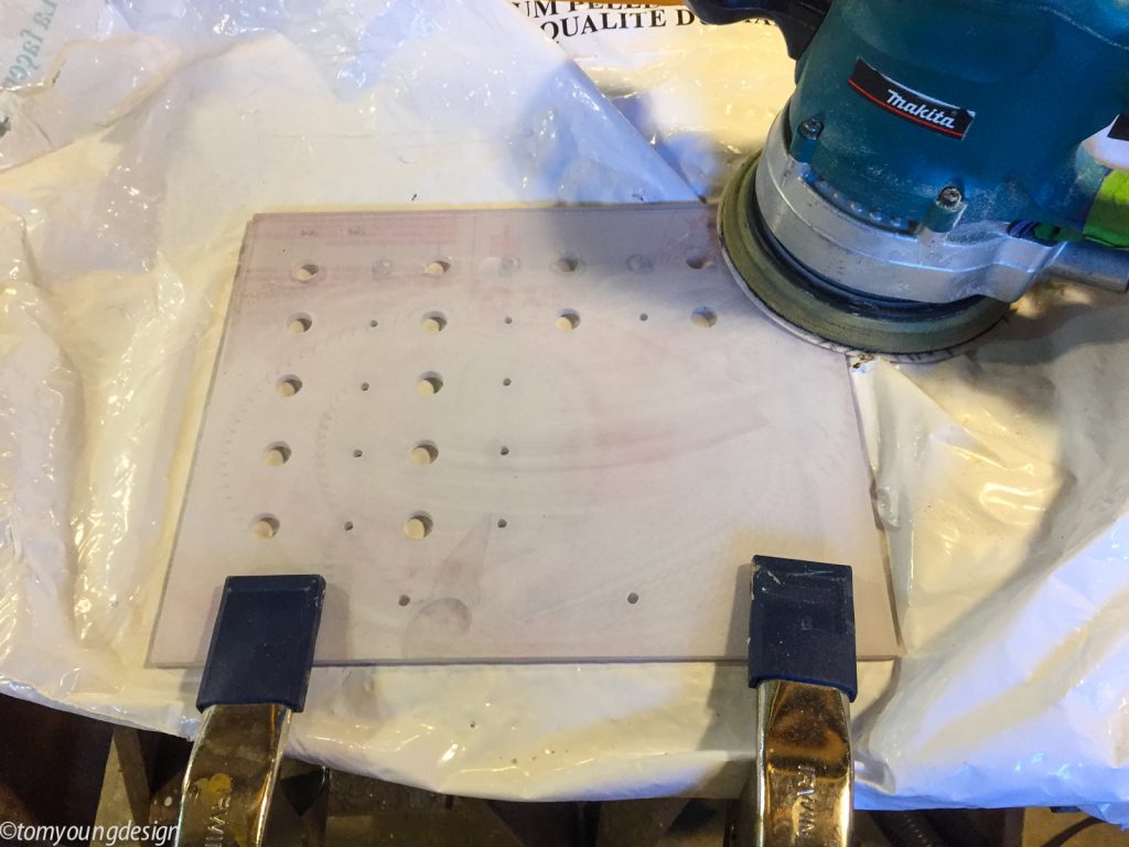
As I’d had success using ¼-inch poly- carbonate for an engine switch panel, this material was an easy choice for the electrical panel. It took some thought, and much trial and error on paper, to find a spacing for the toggle switches and indicator lights so that they and the wiring behind would fit on the small switch panel.
When I was satisfied with the panel’s design, I drilled ½-inch holes for the toggle switches and 11⁄64-inch holes for the indicator lights, sanded the back of the new panel with a random-orbit sander to give it tooth, and spray painted the back with several coats of enamel paint.
After securely mounting the fuse blocks, positive terminal strips, and neutral bus bar, I spent many pleasant winter hours in a warm, bright shop cutting, stripping, and crimping. I tug-tested each newly crimped terminal before fastening it firmly to its new terminal screw. All the new 12-volt DC switch-panel parts, including switches, fuse blocks, terminal strips, and bus bars, are rated to safely carry at least 20 amps at 12 volts DC. All the new wiring inside the new panel (red for positive and yellow for neutral) is 12-gauge marine-grade wire, which is also rated to safely carry a current of 20 amps at 12 volts DC. Using the 12-gauge wire throughout the panel simplified the work and also keeps voltage drop to a minimum.
Onboard wiring
When the warmer weather came, I was able to easily fit the new panel and fasten it into the boat. Then the difficult onboard work began. Access for running wires into the open back of the new panel was a little tight, but much improved over the 1960 version. Under the dark boat cover, I’d spend an hour or two connecting a few circuits. There was no hurry: spring takes its time on the coast of Maine.
My first task was to run the new 3-foot-long #2-gauge main cables from the 5026 fuse blocks to the batteries. The red positive cable from the fuse- box post connects to a marine-rated battery fuse (MRBF) holder bolted to the battery-switch terminal (there is not sufficient space above the battery posts). Next, I cut and crimped the yellow negative cable from the fuse box to the batteries and bolted it to the neutral post. The main switch panel’s neutral bus bar and the fuse blocks are safety rated to 100 amps, so a 100-amp MRBF fuse protects the new cables from the batteries to the fuse box.
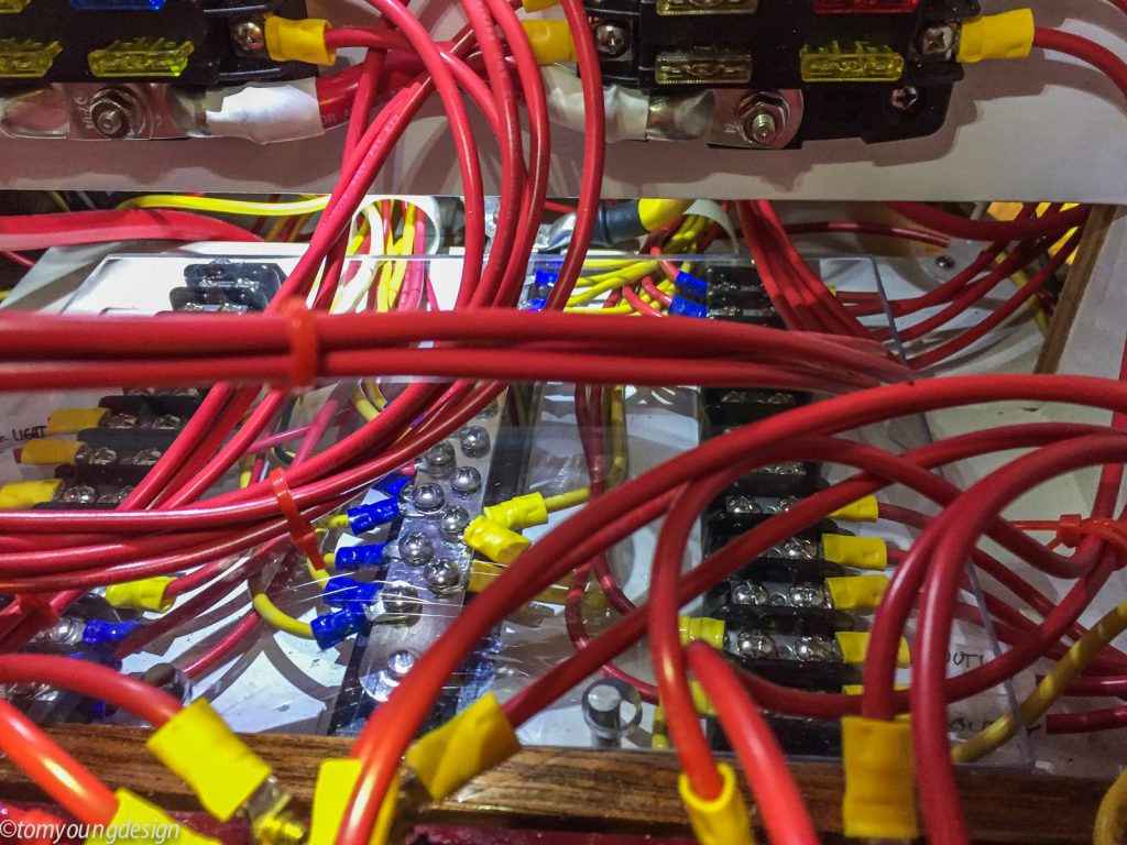
Moving through the panel wiring, I kept testing the hinged switch panel and bundled wiring. For peace of mind, I decided to add a removable ¼-inch Lexan chafe plate in the bottom of the box to cover the terminal strips and bus bars. This clear plate allows me to easily view the connections when the switch panel is folded down, but I can remove it to work on the terminals. When the switch panel is closed and locked, the plate isolates the terminal strips and bus bars from the folded wires behind it.
The new switch-panel box lines up with the engine panel in the cockpit, creating the main wire raceway. There is also some access through the starboard locker and a manhole in the cockpit sole. Running a circuit meant making a few visits to each of these points — extreme boat yoga at times but it was still fun, taken in short doses. I began to further appreciate all the work I’d completed in the shop before the onboard work began.
I examined each new circuit as I connected it to its fuse box. While all the new wiring in the new panel was rated safely above 20 amps, the connecting onboard circuit wiring varied in size. By referencing tables of allowable amperage for the various wire sizes, I installed fuses correctly rated to protect those circuits.
Project creep
A boat accumulates a lot of history over 56 years and three owners. Marine electrical gizmos and their wiring come and go. I discovered unknown problems and rediscovered past deferred problems. This was the time to fix them all. The work grew — that’s the nature of working on an old boat. Soon, the entire cabin was turned upside down and strewn with every tool and spare part.
This process, though it took longer than expected, was invaluable. I traced and eliminated long-unknown dead circuits, secured good old wiring, and cut out and replaced bad wiring and sketchy crimp terminals that came off with a tug. Slowly, as I made many short visits under the cover, dangling wires began to disappear. Even safely fuse-protected wires need to be properly secured. I cut old wire ties, sorted out the wires, and installed new ties.
I connected circuits to the new switches via the new terminal strips and bus bar. Devices that run for 24 hours and have their own switching, such as the VHF radio and the chart plotter, I connected directly to the fused and neutral terminals on the fuse blocks.
As a finishing touch, I applied stick-on labels to the switches and to the ATC fuse blocks, so that someone in the future (I hope that will still be me!) will be able to trace the wiring without much difficulty.
Small LED utility lights are available these days in endless sizes and variety. I fitted one inside the box to illuminate the switches and the interior wiring when the panel is unlocked and hinged down for work. I liked the light so much I added several in the engine space.
It was a joy to finally throw the main battery switches and test my work.
Tom Young, a lifelong sailor, is a design-builder. When he’s not restoring old homes on the coast of Maine, Tom and his family — wife, Mary Anne, now-adult children Mary Jane and Thomas, and a couple of dogs — sail the world-class coast of Maine and New England every season. Tom cares for their 1961 Alden Challenger, Christmas, with a passion.
Thank you to Sailrite Enterprises, Inc., for providing free access to back issues of Good Old Boat through intellectual property rights. Sailrite.com