Insurance against the 0-dark-thirty cartridge change
Issue 115: July/Aug 2017
I well remember the first time I had to change a diesel fuel filter under duress. We were on our first trip away from the dock in our 35-foot new-to-us Columbia 10.7, our first boat with a diesel auxiliary. She had been sitting unused for a couple of years, long enough for the fuel tank to grow a good crop of diesel bugs. The sea was a little boisterous.
A few miles from the dock, the filter clogged and the diesel began to die. Between the tank and the engine was an old Racor filter with a cantankerous O-ring seal. With my head down in the engine compartment and the boat bobbing and adrift, I struggled to get the new filter element in place and the O-ring to seal. From that day on, I lusted for a dual-filter setup that would allow me to switch easily to a clean fuel filter while leaving the clogged one for me to change at my leisure.
I checked many marine stores and catalogs looking for such a beast. All I found were dual-filter systems that could pass 60 to 100 gallons per hour (gph) at prices upwards of $1,500. These were way too rich for my blood and overkill for my little 1/2-gph Yanmar. If I wanted a dual-filter unit, I would have to build it myself.
Parts and placement
I started by looking at individual diesel fuel filters. I wanted the smallest and least expensive one I could find that had enough flow capacity, and ended up with the diminutive Racor 110A diesel/gasoline fuel filter and water separator, rated at 15 gph for diesel and 35 gph for gasoline. It’s possibly overkill for my little Yanmar, but it’s compact.
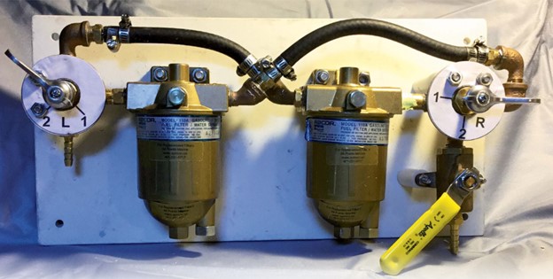
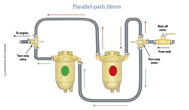
The next step was to develop a block diagram so I could figure out how the filter unit would work and to identify the components I would need. After drawing several scenarios, each requiring different numbers of components, I came up with a design that required two 2-way fuel-selector valves, a ball valve, a handful of plumbing fittings, and fuel hose.
Having settled on the design, I began to source the parts I needed. I learned that it pays to spend some time online researching the best prices. For example, the list price on a Racor 110A is around $155; I purchased mine for $95 from an online diesel-parts supplier.
I rounded up the rest of the fittings only after visiting several marine stores, as many of them didn’t stock the fittings I needed in the quantities I needed.
Assembly
After I’d acquired all the pieces, I trial-fitted them in various ways in search of a compact assembly that would fit in the limited amount of space in my engine compartment. I could have used solid pipe to make all the connections, but I realized it would be a difficult task to get all the fittings uniformly tight and leak-proof, so I made some of the connections with hose.
Once I’d settled on a trial assembly and determined the final size of the unit, I could select a mounting board. I chose 1/2-inch-thick StarBoard because it’s sturdy enough to hold the components, it can be cut and drilled like wood, and it is impervious to water and fuel. I cut a piece 8 inches wide by 16 inches long and drilled a 1/4-inch-diameter hole in each corner for screw-mounting the unit to a bulkhead in the engine compartment. I bolted each filter directly to the board with two 5/16-inch flat-head machine screws, countersinking their heads into the back of the board so I could mount the board flush to the engine room bulkhead.
Bolting the filters directly to the backboard left the selector valves and shut-off valve standing proud of the mounting board. To provide proper support, the attachment bolts would have to run through stand-offs, and that posed a bit of a problem. I tried using nylon stand-offs from the specialty hardware drawers in my local home-improvement store, but the selection was limited. I tried stacking stand-offs of various lengths together and shimming them with washers, but I could never get them quite right and was concerned about stressing the valves or their connections. I finally bit the bullet and purchased a length of acetal-resin tube from McMaster-Carr so I could cut stand-offs to the exact lengths I needed.
Valve settings
To test the assembled components, I removed the drain plugs from the filters and slipped a short piece of hose over the inlet fitting. By blowing through the hose, I was able to determine how to set the selector valves to direct the flow through one filter or the other. I didn’t get the flow right the first time, and had to reassemble one of the filter setups and reorient the selector valve to correct the direction of flow.
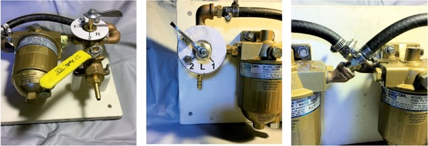
Prior to testing the unit, I bolted blank dial faces to the selector valves. Once I was certain of the correlation between the direction of each valve handle and the direction of fuel flow, I marked the faces accordingly, then drew them on my computer and glued the printout to a thin piece of plywood. A couple of coats of epoxy waterproofed the dials. They are held in place with the machine screws that attach the valves to the board.
Plumbing and proofing
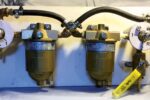
After bolting the filter/valve units to the backboard, I connected them with Coast Guard-rated fuel hose. Fuel hose can have one of four ratings: A1, A2, B1, and B2. To be on the safe side, I used A1 hose, which is the highest-rated and can be used above or below deck. The latest version of A1 hose is labeled A1-15. The hose barbs of the pipe-to-hose fittings were long enough for me to double-clamp the hose connections. When double clamping a hose, it is important that both clamps ride fully on the barbs. If the barb is too short, the second hose clamp can cut the hose where it’s not supported by the barb. By the way, I used only marine-rated all-stainless-steel hose clamps.
It’s important to use a thread sealant on the threaded components. I used yellow fuel-rated Teflon tape on my initial assembly of the filter/valve unit. When I disassembled the joints on discovering I had the selector valve the wrong way around, I found stray bits of Teflon tape inside the joints. At that point, I switched to Permatex Aviation Form-A-Gasket No. 3 Sealant, a liquid thread sealant that my online search indicated was highly recommended.
With the unit completely assembled it was time to test it. Before mounting the board on the bulkhead, I made temporary connections to the fuel inlet and outlet and ran the engine with the assembly sitting in a pan, to catch any leaks rather than put fuel in the bilge.
My dual switchable filters give me peace of mind from knowing I won’t be powerless for long should a filter ever become clogged from dirty fuel.
Paul Esterle has been boating since the early 1960s. Starting out with a wooden Sunfish, he graduated to stripper canoes and sailing wooden Folkboats on Lake Erie. Paul is currently based at the head of Chesapeake Bay, where he works on and sails his small fleet of classic plastic sailboats.
Thank you to Sailrite Enterprises, Inc., for providing free access to back issues of Good Old Boat through intellectual property rights. Sailrite.com