A little stiffness could have become a big problem
Issue 113: March/April 2017
We had been tied to a dock for several weeks enjoying the city of Seville, Spain. It was a day just like any other day: I climbed aboard, swung my leg over the bow rail, and, in what has become almost a ballet for me, grabbed the furled headsail to swing myself around onto the foredeck. I don’t really know why I do this, it’s just something that has developed over the last 30 years. But this time I froze! The furled sail did not swing with me as usual. A slight twist of my arm resulted in a soft “snap.” All was well, just a fluke. I repeated my ritual the next day and, to my surprise, Entr’acte again refused to dance with me! For the rest of the day, the furled sail turned freely, but in the mornings I felt a definite click when I rotated the furled sail.
We installed the ProFurl NC-32 furler on Entr’acte, our Nor’Sea 27, a whopping 17 years and thousands of miles ago. It has seen us through the most severe conditions and had never once given the slightest hint of a problem, until that morning in Seville. For a few moments I deluded myself into thinking the problem was simply the result of airborne sand or debris that had come to rest in the perfect spot to cause this slight jam. Then I heard the voice of rationality: “The reason does not matter! Slight as it is, it still jams!”
A jammed furling gear on a dark night ain’t pleasant! It can lead to serious damage or injury. We were lucky to get this warning. I learned my lesson on the River Seine: If I even suspect a problem, I fix it right then and avoid disaster. (See “Dead in the Water,” January 2015.)
Dire warnings
When we purchased our ProFurl, we were warned that repairing it ourselves would be impossible, but we insisted on buying a complete rebuild kit so we might have a fighting chance “out there.” Operating on my brother-in-law’s theory that anything someone has put together can be taken apart, Ellen and I tucked the parts away and decided to cross that bridge when we came to it.
Throughout our travels, other cruisers repeated the warning:
“You can’t fix it yourself.”
“You need special tools.”
“It’s too old. Parts are no longer available. You have to buy a new one.”
“I sent it to two dealers and neither would touch it, so I threw it away.”
This is a shame, because the repeated warnings are unwarranted. Old ProFurl units are surprisingly easy to repair right on board and everything you need can be purchased from any auto parts store.
I wanted to prove my assertion that this ProFurl unit can be simply and easily rebuilt with widely available parts. I disassembled my unit and, instead of installing my own parts kit, took the original parts to my local NAPA store. In less time than it took me to eat a bag of their free popcorn, the staff put together a duplicate replacement kit (minus the two reuseable spacer rings) for less than $60. Better still, they assured me that the bearings and seals are standard parts, available all over the world.
For perspective, after completing this project, I did find a source selling an authentic rebuild kit for $99 — two of these are needed — along with a quote to perform the rebuild for $500.
Service parts
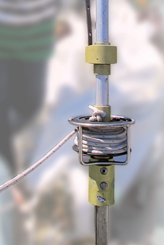
Looking at the furler from the outside, it is difficult to comprehend how these units are put together. Once taken apart, though, the ProFurl roller furling system has surprisingly few parts: four rubber seals, four bearings, six snap rings (four external, two internal), and two spacer rings (photo 1). That’s it! All four seals are the same, as are all four bearings. The parts are divided equally between the upper and lower units. Looking at my parts kit in the bag, it was immediately obvious how things were put together.
The most important thing to understand is that when working on anything that has a seal, you must accept the fact that you cannot remove any seal without destroying it! The secret is to remove the seal without damaging the rest of the unit. The rest of the job is just a matter of paying attention to the sequence of steps and being careful. The challenge I faced was to determine the proper disassembly sequence and not work my way into a corner and ruin the project.
The tools
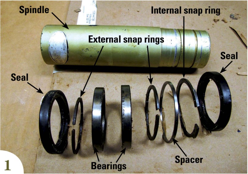
In the interests of Good Old Boat readers, I limited myself to using only tools that any boater would carry on board or have at home. At the top of the list is a digital camera. Otherwise, only a couple of inexpensive specialized tools are needed: a set of loop hooks and picks for pulling seals (photo 2) and reversible snap-ring pliers. They are available from any auto parts store.
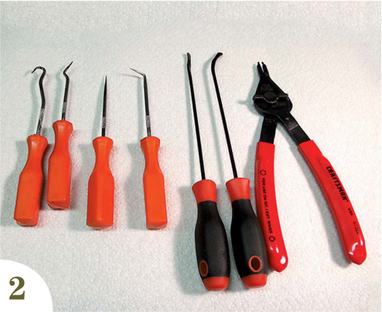
Snap rings (also called circlips) come in two forms that look similar but differ in the way they are installed and removed: external (squeeze the pliers to expand) and internal rings (squeeze the pliers to compress). Both types are standard items and available almost everywhere. With reversible pliers you can remove or install them both. Buy a good pair. For a furler larger than our NC-32, you might need a bit more power (photo 3).
The ProFurl components
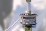
The ProFurl system has two swivel units. Their internal workings and their disassembly/assembly sequences are identical. The only difference is that, to disassemble them, you work from the top of the upper unit and from the bottom of the lower unit.
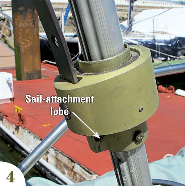
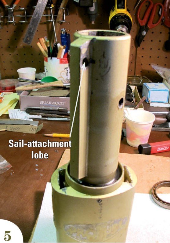
Before you do anything, carefully mark each unit to show which end is up. On the upper unit, the sail attachment lobe is on the bottom of the center spindle (photo 4). Conversely, the sail attachment lobe on the lower unit is on the top of the center spindle (photo 5). It is very important that you keep this straight in your mind.
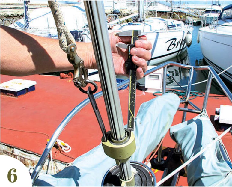
Take photos of each unit from the top and from the bottom. These photos will be of help when you replace the seals. Use calipers to measure the distance from the top and bottom of each unit to the top of each seal (photo 6). Write these measurements down. If you set the new seals too shallow, they will pop out. Setting them too deep will compromise the seal.
Disassembly
For simplicity, disassemble one unit at a time, starting with the upper unit and working from the top.
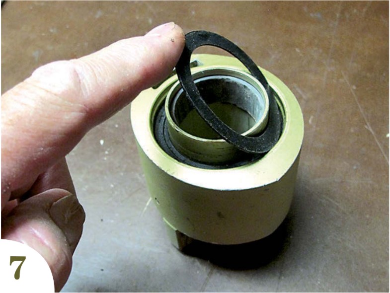
• Remove the sun cover — it lifts right out (photo 7).
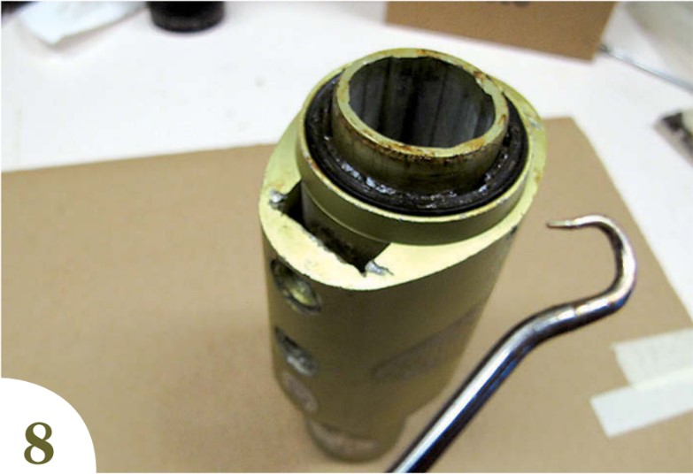
• Remove the top seal. Don’t try to save the seal. It’s dead, that’s why you are doing this job.
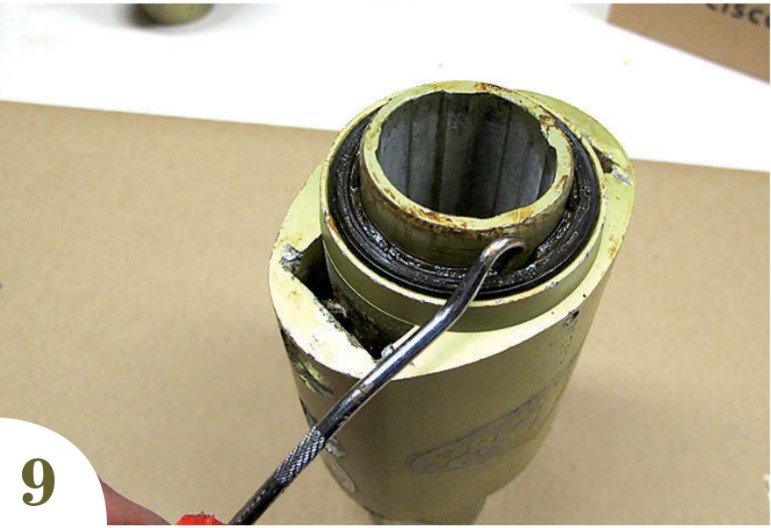
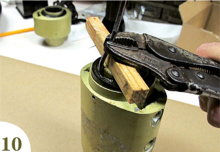
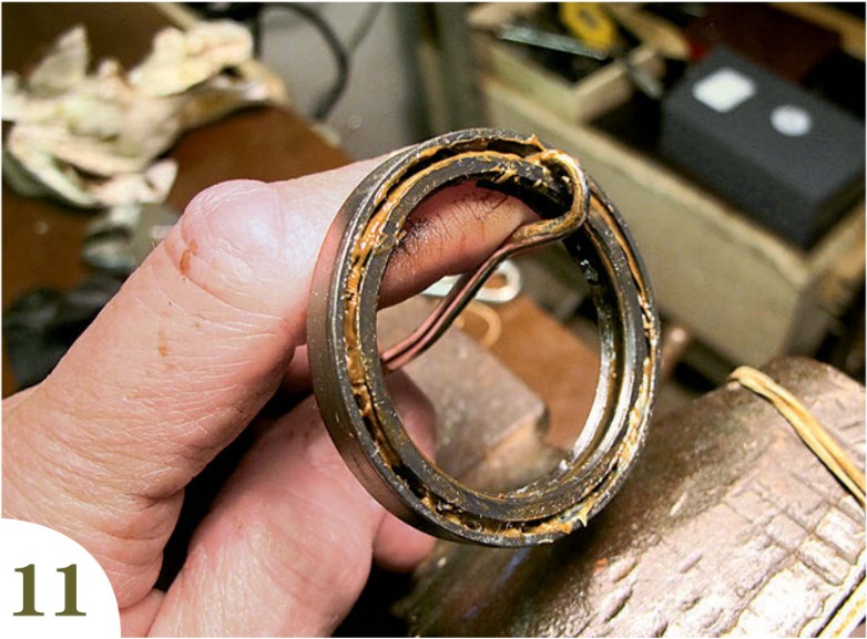
Slide the loop-hook tool between the spindle and the inner lip. Twist the hook outward so the hook engages the groove on the underside of the seal. Use a piece of wood as a fulcrum and lever the seal until the old and dry rubber-to-metal bond gives way. You might have to try this at several positions around the seal before it finally lets go. Be careful. Do not scratch the center spindle. Scratches will degrade the watertight integrity of the new seal (photos 8, 9, 10, and 11).
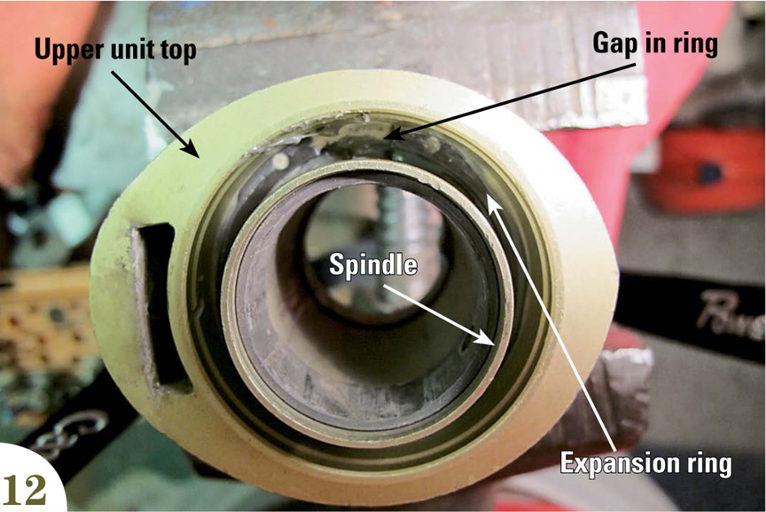
• Use a Q-tip and brake cleaner to clean out the cavity as thoroughly as possible. You want a clean, unobstructed view of the interior snap ring (photo 12).
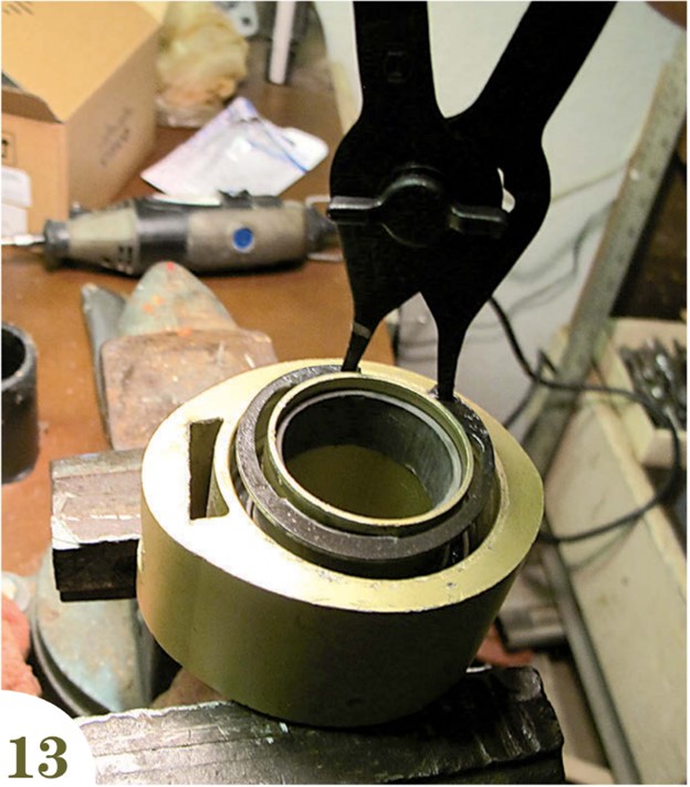
• Set the pliers to “squeeze to compress.” Press the points firmly into the holes of the ring and squeeze smoothly until the ring comes free of the internal groove. It should almost, but not quite, touch the center spindle. Carefully withdraw the ring. If the plier points tend to slip out of the holes, there is still too much grease or you need thicker points. Keep the ring perpendicular to the spindle as you withdraw it.
If the ring slips and becomes lodged at an angle, you could have a fight on your hands. This is especially true on the lower unit, due to the longer spindle and the confined space. This is the only scary part of the job (photo 13).
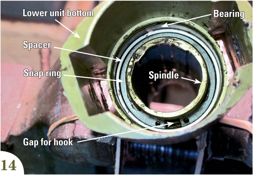
• Clean the cavity again until you can see clearly and study the snap ring and spacer (photo 14). The snap ring fits perfectly inside and rotates freely within and independently of the spacer. This is important. If the snap ring does not fit perfectly inside and rotate freely on re-assembly, the unit will bind.
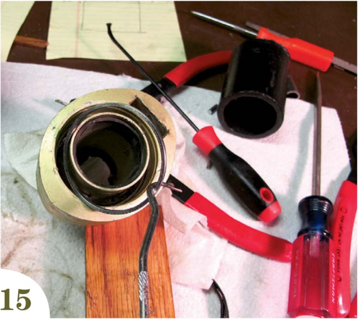
• If the area is free of dirt and grease, a simple tap on a table will cause the spacer to drop out. Otherwise, use the 90-degree hook tool to extract it (photo 15).
• Turn the unit upside down and use a small block of wood to gently tap the spindle downward 1⁄16 inch and stop (photo 16). Turn the unit right side up.
• Set the pliers to the “squeeze to expand” position and remove the internal snap ring, once again holding it perpendicular to the spindle.
• Turn the unit bottom side up and break the bottom seal free of the housing, as you did the top seal, but do not try to remove the seal completely.
• Set the unit right side up on a vise with the center spindle free to rotate. Gently tap the spindle completely through the housing. The spindle, second snap ring, and bottom seal will come out as a unit, leaving the bearings behind (photo 17).
• Tap out the bearings. For my upper unit, I used a short length of PVC pipe that was the exact diameter of the bearings. A few gentle taps and it was done. For the lower unit, I used the tried-and-true bearing removal technique: a flat cold chisel and gentle taps around the circumference of the bearing. One light tap at the 12-, 3-, 6-, and 9-o’clock positions and repeat until the bearings drop free. Do not bang. One gentle tap at each point is all it should take. If the bearing becomes lodged at an angle, do not pound but simply turn the unit over and tap the offending side until the bearing is again straight, then continue. If the bearings are rusted in place, you may have to soak the unit for a few hours in WD-40 or PB Blaster (photos 18 and 19.)
• The final step is to remove two tiny balls from each unit. They seal small holes that allow for the venting of air and excess grease on reassembly. These balls must be removed prior to reassembling the units.
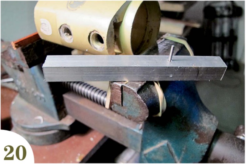
Press the balls out from the inside using a simply-made extraction tool. Find a nail or old drill bit that fits exactly into the vent hole from the inside. Cut it to a length of 3⁄4 inch and press or glue this pin into a short length of 1⁄2-inch-wide wood or metal. A tight fit without wobble is best (photo 20).
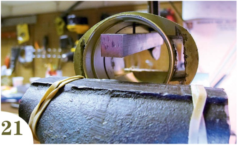
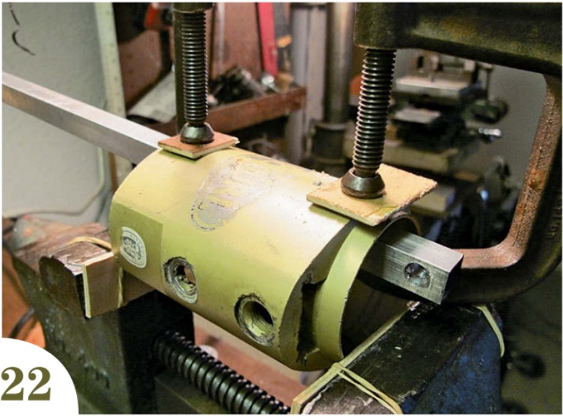
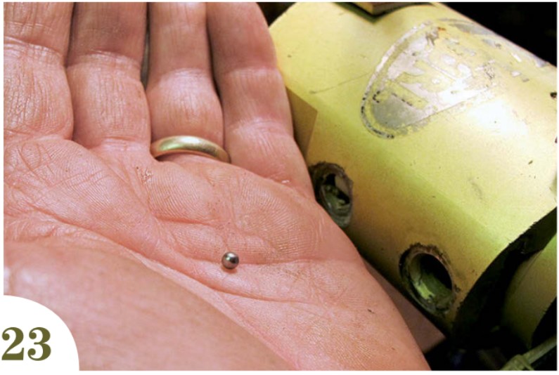
Fit the pin into the vent hole (photo 21) and hold each end of the tool in place with a small C-clamp (photo 22). Use the clamp nearest the vent hole to slowly press out the ball. Watch the ball. There is no eruptive force here but a bit of masking tape over the ball will keep it under control. Resist the temptation to just squeeze the rod with pliers. You do not want to lose these balls! Store them in a cup for safety (photo 23).
Before re-assembly
Clean the unit thoroughly, inside and out, with brake cleaner. Remove every trace of grease, oil, and sludge from every surface and also from your hands, gloves, pliers, and snap rings, especially the pins of the pliers and the holes in the snap rings. Cleanliness is vital!
Inspect the center spindle where it comes into contact with the inner lips of the seal for scrapes, nicks, gouges, and burrs — anything that could compromise the integrity of the seal. If you find anything serious, you can fill it with epoxy and smooth it with 800-grit wet/dry. Do not do this unless you must!
Should you need new spacers, know that, other than their precision measurements, there is nothing special about them. Any machine shop can duplicate them if necessary. Despite the muck I found in my lower unit, both the spacers and all the snap rings appeared like new and were reuseable.
Reassembly
The assembly process is exactly the reverse. (Don’t you just love that term?) It really is that simple. However, there are some caveats, so take it slowly and carefully.
First, make certain that you know which end is up! Inspect the interior of each unit and note the following:
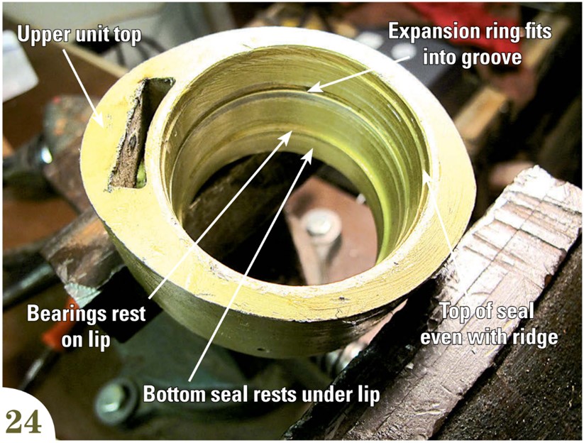
Upper unit
Identify the ridge at the bottom of the unit that serves as the stop for the bearings and also for the bottom seal.
Locate the groove into which the expansion ring must sit. It is critical that the ring sits in this groove all the way around.
Note the ridge at the top of the unit that shows the proper depth for the top seal — the top of the seal must line up with this ridge, otherwise it will eventually pop out due to the slightly larger diameter above the ridge (photo 24).
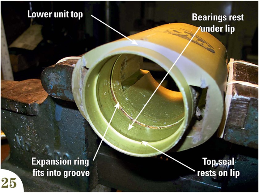
Lower unit
Note the ridge at the top of the unit that serves as the stop for the bearings and the top seal.
Look for the groove into which the expansion ring must sit. It is critical that the ring sits in this groove all the way around.
Find the small lines at the top and bottom of the unit. These lines indicate exactly where the tops of the seals should be after assembly. The tops of the seals must press to these lines or they will come adrift (photo 25.)
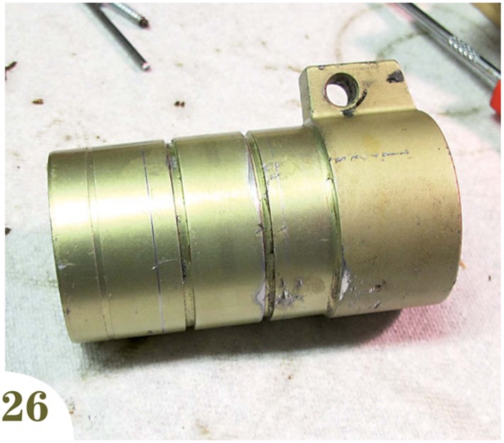
Center spindle
Note that, on both units, there are two grooves around the center spindle. The snap rings must sit perfectly inside these grooves all the way around. If they do not, the unit will bind (photo 26).
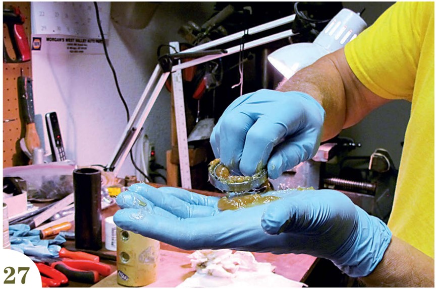
Reassembling the upper unit
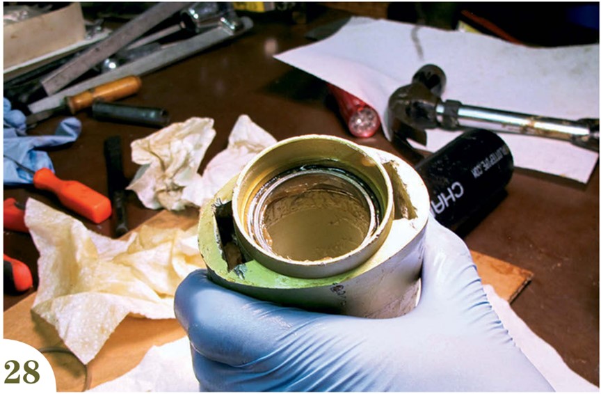
• Unless your new bearings are pre-packed and permanently sealed, pack the new bearings with grease and gently tap them into the casing one at a time until both bearings come to rest on the lip (photos 27 and 28).
• Put on a new pair of gloves and thoroughly degrease your pliers and snap rings. I cannot overstress how important this is. You do not want the rings to slip off the pliers and become lodged inside the unit.
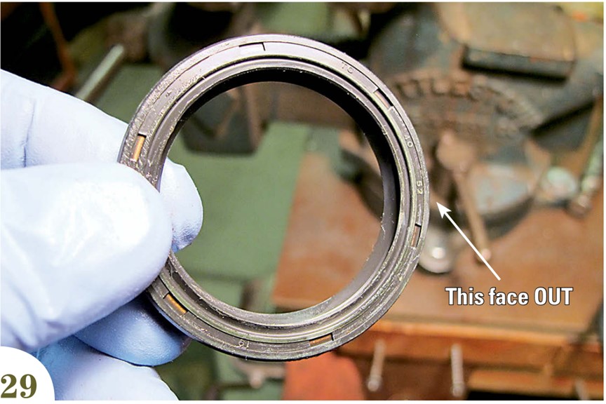
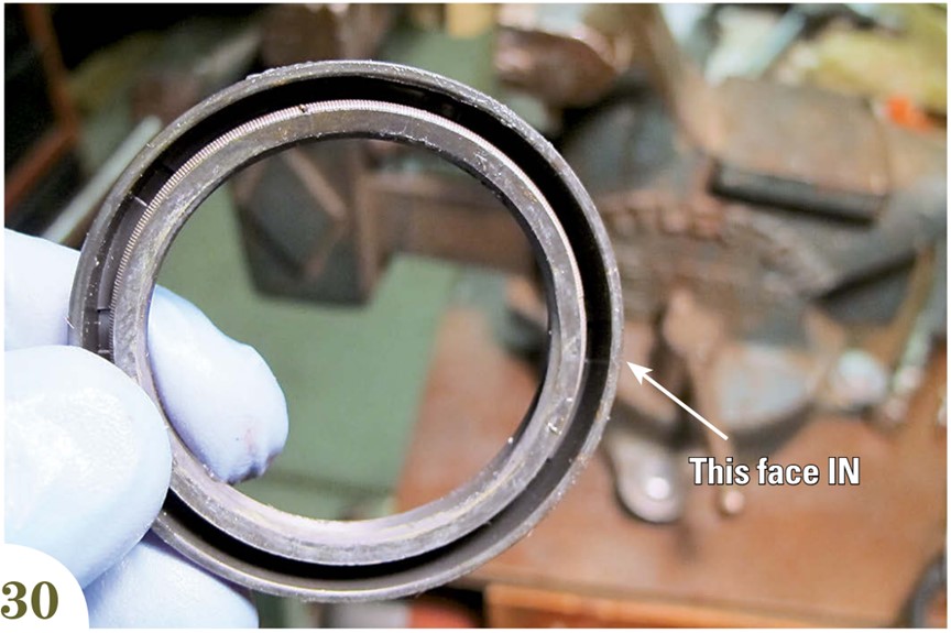
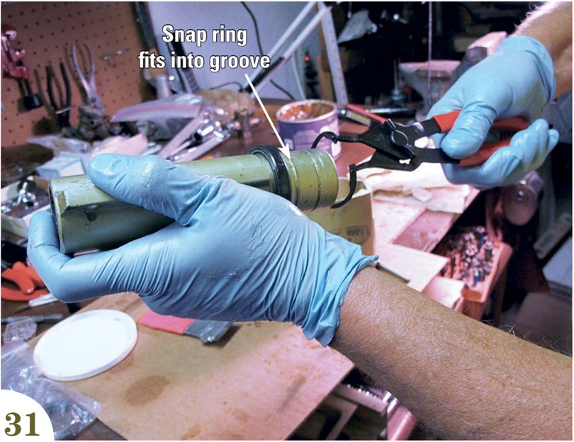
• Apply a very light film of grease to the spindle. Slide the bottom seal (photos 29 and 30) onto the spindle and install the lower snap ring (photo 31).
• Turn the upper unit bottom-up. Slide and twist the spindle into the casing. Press in the bottom seal until it is even with the edge of the casing and stop! Make certain the seal is even all the way around. If thumb pressure is not enough, tap the seal into place with a flat wooden dowel, working around the circumference.
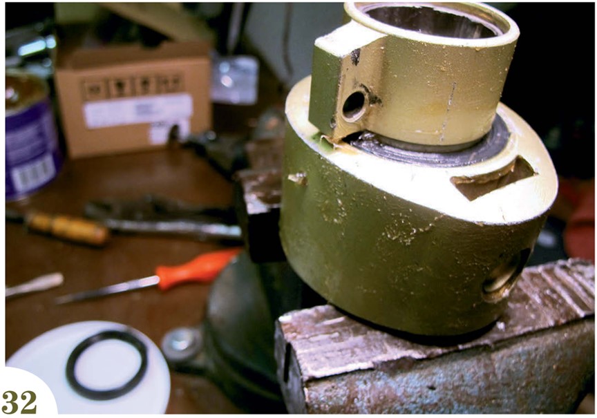
• Gently tap the spindle until the sail-attachment lobe almost touches the edge of the casing and stop! This will better expose the groove for the next snap ring (photo 32).
• The bearings will now have moved away from their inner lip stop. Turn the unit over and use the cold chisel to gently tap them back against the stop. Install the upper snap ring into the spindle groove. With the chisel, tap the ring at 1-, 6-, and 11-o’clock to make certain it is in the groove. A gentle “snap” at each point tells the tale.
• Gently tap the bottom of the spindle until the snap ring just makes contact with the bearings. Rotate the spindle. It should feel stiff but smooth.
• Install the spacer ring. It drops right in. Rotate the spindle and make certain that the snap ring sits perfectly inside the spacer. If it does not look exactly like photo 14, the snap ring is not completely in the groove! If you hear or feel any grinding, back up a few steps and try again.
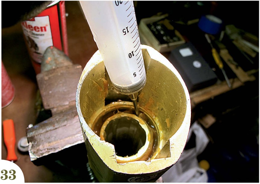
• Install the expansion snap ring, using the pliers in “squeeze to compress” mode to place it in position. Make certain the ring snaps completely into the groove in the casing. Add a layer of grease around the circumference (photo 33).
• Rotate the spindle in both directions. All should be smooth and quiet. Up to this point you can completely disassemble the entire unit with no loss except for your time.
The last step
Be absolutely certain you are ready before you install the last seal. There is no backing up! Once this seal is installed, you cannot remove it without destroying it!
• If all is well, cover the circumference of the snap ring with grease, press the seal into the casing and, using your thumbs and the wooden dowel, gently tap around the circumference until the top of the seal is even with the edge of the casing. Rotate the spindle a few times in both directions and stop! Enjoy a cup of coffee while the grease flows and equalizes.
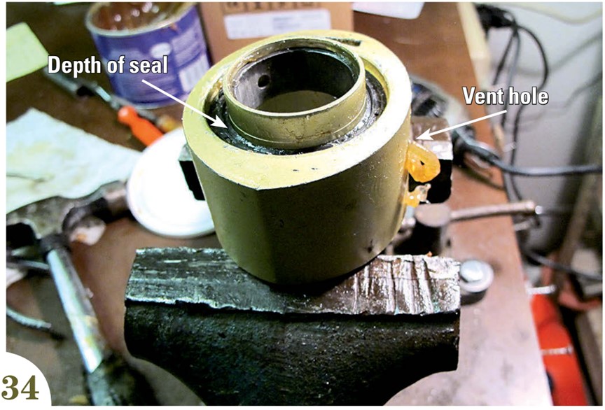
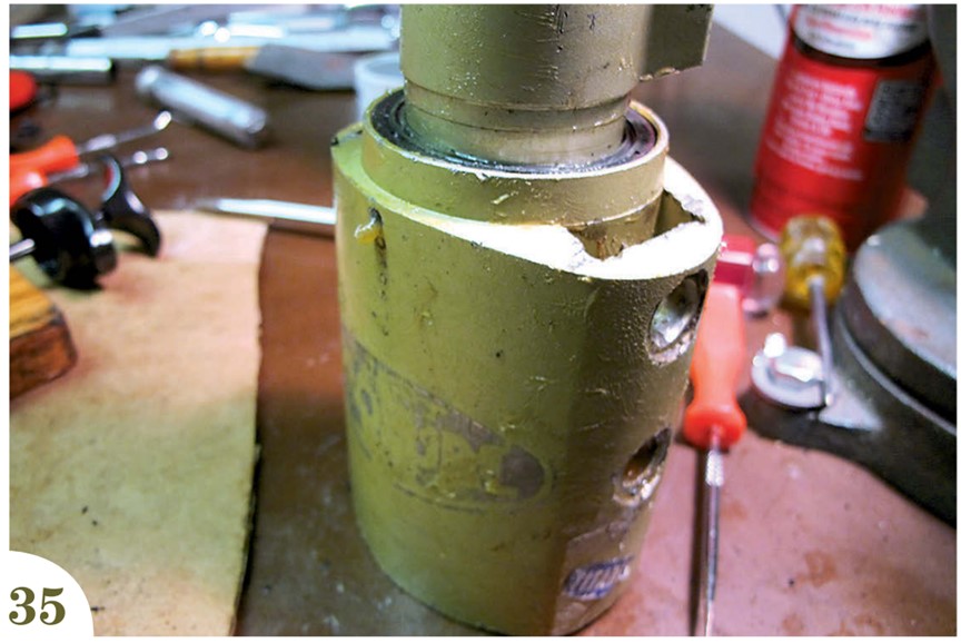
• Tap all the seals to their proper depth, at one end even with the ridge and at the other when it comes into contact with the inner lip. Refer to the photos and measurements you took before you disassembled anything. Rotate the unit a few times and allow the grease to equalize and flow through the vent holes (photos 34 and 35).
• Using a nail set, gently tap the vent balls into their holes so they are flush with the casing. There is no danger of tapping them through to the inside.
• Lay the sun shield on top of the top seal of the upper unit and install the halyard lifting ring. If for some reason you do not have a sun shield, make one out of any dark plastic you can find. Without a shield, this seal would be exposed to a lot of harmful sunlight.
• Install the drum, basket, and link plates on the lower unit.
Going slowly and carefully, it should take about two hours to rebuild each unit. After that, you can sit back and bask in the glow of a precision job well done and congratulate yourself on having saved somewhere between $500 and $2,500. And you might also have avoided a lot of grief and drama on a windy night!

Furler TLC
I was pleasantly surprised at the longevity of our ProFurl unit. Seventeen years of ocean passages is a long time for any device with more than one moving part. How did we get so lucky?
First, we made certain to install the sun cover over the top bearing of the upper unit. The upper seal of this unit is exposed to the sun, and sun is the enemy of all rubber.
The lower unit also lives in a brutal environment. The bearings are constantly subjected to salt water under pressure from wave action, from above and below. Then there is rainwater. Our practice has always been to remove both units and stow them below whenever Entr’acte is laid up. This dramatically reduces their exposure to the sun, which degrades the seals, and rain, which can seep past the seals over time.
It takes only a few minutes to remove and stow the ProFurl, and it seems to have paid dividends.
Ed Zacko is a Good Old Boat contributing editor. He and Ellen met while playing in the orchestra of a Broadway musical. They built their Nor’Sea 27, Entr’acte, from a bare hull and since 1980 have made four trans-Atlantic crossings and one trans-Pacific. They spent the last five seasons based in Seville, Spain, sailing in and around the Mediterranean and playing in the jazz clubs of Spain, France, and Morocco. Last September, they shipped themselves and Entr’acte to the U.S. Now in Phoenix, Arizona, they maintain a busy concert schedule throughout the Southwest U.S. Follow them on www.enezacko.com.
Thank you to Sailrite Enterprises, Inc., for providing free access to back issues of Good Old Boat through intellectual property rights. Sailrite.com