Installing an outboard motor well on a 28-foot cruiser
Issue 27: Nov/Dec 2002
WHEN OUR BOATS WERE HAULED for routine maintenance at a Trinidad boatyard recently, my friend, Theo, asked me for suggestions on how to improve his outboard motor installation. On Islander, his 1972 Hong Kong-built Taipan sloop, instead of an inboard motor he has a 5-hp, long-shaft Mariner hung on a standard adjustable transom bracket.
“You know, I don’t like inboard motors,” he said, “but this outboard is a real pain. In any kind of sea the prop gets lifted out of the water one minute and then, as the bow lifts, the motor gets dunked under water and stalls out. It’s also difficult to lift it out of its storage locker and hang it over the stern to set it up when the boat is bouncing around. There must be a better way.”
We both have similar, full-keeled, 28-foot fiberglass cruising sailboats. Both of us had removed our original inboard motors years ago and replaced them with outboards. I had removed my Pearson Triton’s Atomic 4 partly because it had become a maintenance nightmare and partly because I wanted to have a pure uncomplicated sailing experience. (See “Twice Around in a Triton,” Good Old Boat, May 2001.)
For more than five years I cruised far and wide with only sails and a sculling oar; I proved to myself that it was practical and rewarding. When my cruising style changed from primarily making long offshore passages to doing more coastal cruising and river trips, I reluctantly re-entered the motoring world by purchasing a 3.3-hp outboard. The noisy little beast normally lay forgotten in a cockpit locker. When needed, I hung it on an adjustable stern bracket. It did work . . . sort of. Besides the problems Theo mentioned, there is the question of aesthetics; it’s just plain ugly, hanging there on the stern like an afterthought. In addition, there is the possibility of theft; an envious Brazilian fisherman had pinched my outboard a year earlier.
Taking measurements
I had been thinking about this problem for some time, so when Theo asked for help I was ready and enthusiastically leapt aboard Islander with tape measure and notepad. Theo eyed me quizzically as I crawled around measuring the overhang of the transom, emptying his lazarette locker and disappearing inside it. When I emerged, I told him my plan: “I can make an outboard well inside your aft cockpit locker.” After discussing the extensive modifications necessary and the estimated cost, he said, “Do it,” and left his cherished Islander in my hands while he flew home for a spell of work in Switzerland.
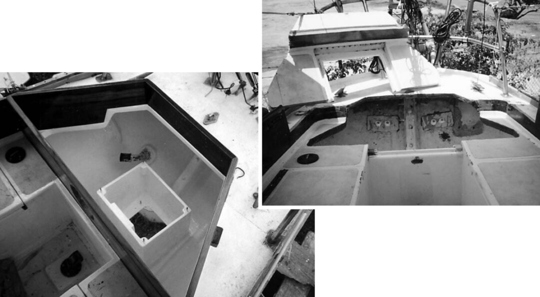
From my measurements, I knew the well would need to be placed as close as possible to the forward vertical bulkhead of the aft locker. The access hole in the deck needed to be as large as practical to allow adequate ventilation while the motor was running and to permit access to the farthest recesses of the locker while the motor was in place.
It was probably best that Theo was not around to see the destructive stage of the job that began when I cut a huge hole into Islander’s afterdeck. “It looks much worse than it is,” I replied when one neighbor asked, “Does Theo know what you’re doing to his boat?”
Once I had cut this large section of deck out with a jigsaw, the real dirty work began. Using #36 grit pads on a grinder, I took most of the inside of the locker down to bare fiberglass. To protect my skin and lungs from fiberglass dust, I wore a full Tyvek suit with hood, goggles, and respirator. Next, I carefully measured for the placement of the hole in the hull needed to accommodate the motor’s shaft. Originally I planned to cut a circular hole so the motor could easily pivot to provide side thrust when needed to turn in tight quarters, such as when a current has you pinned against a dock. Unfortunately, further measurements indicated that, because of the angles involved, this would not be possible.
Smallest hole
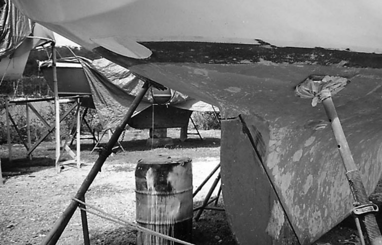
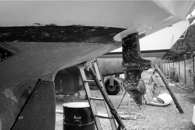
So I cut as small a hole as possible that would still allow clearance for the prop. I saved the slightly wedge-shaped rectangular fiberglass cutout, cut it in half fore and aft, and shaped it to fit around the outboard shaft at the appropriate height.
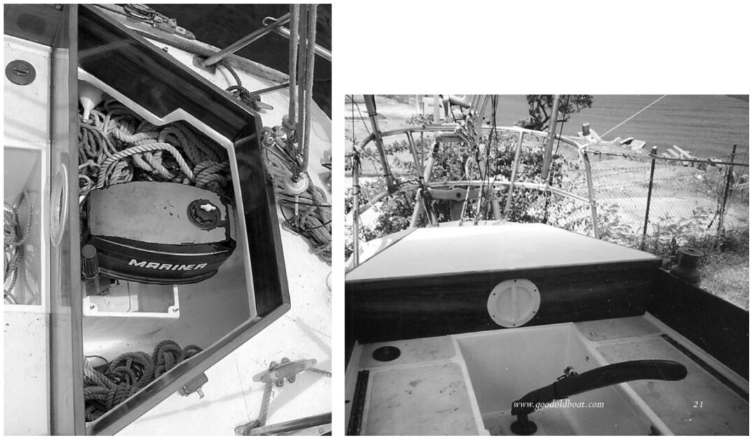
I stiffened the cutout pieces with extra layers of epoxy-saturated fiberglass and attached them to the shaft with angled stainless-steel brackets and 1⁄4-inch bolts. Although the outboard will not always be kept in its well, these new flanges are meant to stay permanently attached to the motor. When the motor is lowered into position, these flanges make a flush fit with the hull, ensuring minimal turbulence and preventing waves from entering and flooding over the inside of the well into the stern locker. The slight gap around the edge is sufficient to allow the motor’s cooling water to drain out.
Holding the motor temporarily in place, I measured for its exact placement. Ideally, the motor should sit as low as possible to ensure that the prop remains under water when choppy seas cause the boat to raise her stern. The motor should also sit low so the deck hatch box does not need to be built excessively high to fit over it. On the other hand, the motor should be situated as high above the waterline as possible to prevent it from being flooded by following seas or when the boat is heeled under sail. I struck a reasonable compromise by placing the prop about 10 inches below the waterline.
Working with cardboard, I made templates for the four sides of the well. The top of the well worked out to be about 18 inches above the waterline. Three of the templates were then transferred to pieces of 1⁄2-inch marine plywood and cut out. The fourth piece, which was the forward end of the box to which the motor would be mounted, needed to be stronger, so for it I used 3⁄4-inch plywood. At the top portion of this piece, where the motor clamps would rest, the thickness of the wood was doubled to 1 1⁄2-inches. The plywood was then sealed with epoxy resin and glassed into position using several layers of medium-weight fiberglass mat, chosen because it can be made to lie flat on uneven surfaces more readily than cloth.
Epoxy only
Although it’s considerably more expensive than polyester resin, I used only epoxy laminating resin because of its better strength and adhesion. To fill gaps and corners I mixed talc-thickened epoxy to the consistency of peanut butter and applied it with a putty knife. Prior to applying the epoxy, I used rags soaked in acetone to thoroughly degrease all surfaces.
To complete the box I block-sanded the top edge perfectly level and epoxy-bedded four 1⁄4-inch bolts into holes drilled 2 inches deep into each top corner. The bolts stood proud by 1 1⁄2-inches, and their heads were cut off so they could be used as alignment studs for a lid held down with wing nuts. This lid has a rubber gasket under it to seal the box and prevent incoming water from entering the boat when the motor is not installed.
The hull also needed a flush-mounted plug to seal the cutout when the motor is not in place. This I made by cutting out a piece of plywood from a paper template that matched the hole and gluing it onto a larger plywood backing. With the plug held in place by a similar system of inward-facing studs, I ground the plug’s outside surface to match the contour of the hull. The plug was sealed against moisture with a coat of epoxy resin and then painted.
This plug is near the waterline but I did not try the difficult task of making it 100-percent watertight. Instead, I expected it only to stop the main force of surging water and provide a smooth surface for water to flow past undisturbed. Whatever water does get into the box can seek its own level and will, in any case, ultimately be stopped by the gasketed top lid.
Before going further, I had to modify the stern locker’s bulkheads to ensure this locker was entirely watertight and isolated from the bilge in case of accidental flooding over of the well. I filled all gaps in the bulkheads with my epoxy-filler mixture and then used fiberglass mat and resin to make it all watertight. For safety, I installed a drain hose leading from the locker floor to the bilge with an in-line shut-off valve accessible from the cabin. This way the locker could drain normally into the bilge or be shut off if there were ever any uncontrolled flooding.
Ever since experiencing my first storm at sea, I have realized that all cockpit lockers should be constructed this way. When a boat is knocked down, pooped by a following sea, or held over flat by force of wind, the cockpit lockers may fill the bilges so fast with water that you risk sinking the boat. At least with the drain valves shut off, there is a limit to how much water can get in the boat.
The hatch box
The next step was to construct a box around the access hole in the deck to raise the hatch high enough to clear the top of the motor. Because of the motor’s height, I needed to add about 5 inches along the rear over the afterdeck, and 9 inches along the front edge where the hatch intruded on the cockpit seat area. Trinidad has its own sustainable teak farm that sells teak at less than half the cost of teak sold in the United States, so I lavishly used 1 1⁄4-inch-thick teak planks for the box’s sides. The upper lid of 3⁄4-inch plywood was then fit over this, trimmed with teak, latches, and a rubber gasket.
Note that when measuring for the height of the hatch box, you need to take into account any extra clearance required by the throttle arm, although usually the handle can be operated while folded back. A round plastic access hatch is located on the forward side of the box to provide access to the motor’s starter cord. Final detailing involved painting the inside of the locker with epoxy primer and two-part urethane paint. The locker lid got a finish coat of nonskid polyurethane. I coated all teak with four coats of clear polyurethane.
It took about 70 hours to complete this job, and we were both pleased with the results.
Recently I had an opportunity to test the practicalities of this installation when Theo asked us to sail Islander from Venezuela to Brazil. The system performed better than expected on the 6,800 mile cruise that took us to the eastern tip of Brazil via Bermuda, the Azores, and the Cape Verde Islands. When approaching a landfall, we could easily place the motor in the well, and seawater never flooded over the well into the locker.
Eliminating drag
On each offshore passage, once clear of land, we stowed the outboard in a cockpit locker to eliminate drag and to protect it from the corrosive effects of sloshing seawater. For this reason, and to save my back, I would not choose a motor that is too heavy or too large to lift. Since the motor cannot pivot back if caught on an obstruction, it makes sense to reduce the risk of unnecessarily dragging it long distances through the sea while under sail. In this case, the hull plug is locked in place to present a strong smooth external hull surface. The top of the well is then sealed with its gasketed lid. Although there should not be any appreciable water intrusion into the main locker, the locker drain valve is left closed and can be checked and drained occasionally as needed.
Around the sides of the well there is ample storage space for ropes and fenders . . . nearly as much as before the well was added, because with the larger hatch, more of the locker’s corner space is accessible. The upper hatch is held firmly in place by sturdy lockable latches on either side.
When the motor is needed, the top and inner hatch lids and the hull plug are removed, and the motor is set in place and secured. The main hatch lid is set aside, and the plastic access hatch for the starter cord is removed. These hatches are normally left open to provide the engine with enough ventilation to operate properly. To protect the engine and locker from rain and spray, we left the main hatch on but propped open slightly at one end to provide the motor with the fresh air it needed to run. Alternatively, a hose could be led from the air intake to an outside vent to allow the motor to be run with the hatch closed.
Operates normally
The motor operates in forward and reverse as normal and steering is done by the tiller. In order to turn the motor for side thrust, it must be put into neutral and the boat brought to a stop. Then the motor clamp screws are loosened and the motor raised 1 1⁄2 inches by setting it on a spacer block. This raises the motor shaft flange clear of the hull and the motor can now be re-clamped, engaged, and swiveled. Normally, I would not bother with this unless doing close-quarter maneuvering. Still, it is possible to use this swivel function, which is one of the advantages outboards have over fixed inboards. Another reason not to allow the motor to swivel in normal use is to prevent it from accidentally turning sideways when sailing at speed, causing high side loads on all components. With the motor seated in its normal position, its flush, rectangular-shaped hull plate prohibits any accidental swiveling. To safely remove the motor when under sail, it is necessary to bring the boat nearly to a stop by heaving to.
This project was such a success that I hoped to repeat it on my own boat. Unfortunately, my Triton lacks enough clearance between the rudder-post and transom. Obviously, this alteration will not be suitable for some other boat designs either; careful measurements need to be made of rudder location, waterline height, and existing locker layout before any work is begun.
The advantages of the well versus hanging the motor on the stern are obvious. For those who do not need to motor long distances or need high power output, this system even has advantages over an inboard diesel. An outboard saves a great amount of space and weight. It is cheaper to buy and maintain. Repairs are easier. When it comes time for a new motor, installation is a snap. If you are going to have an outboard motor for your dinghy, one motor might serve both purposes. Or you can carry two outboards of same or different size and always have a standby ready in case of breakdowns. Try doing that with a diesel inboard! An outboard now located inboard provides the best of both worlds.
Thank you to Sailrite Enterprises, Inc., for providing free access to back issues of Good Old Boat through intellectual property rights. Sailrite.com