Enjoy lots of pure fresh water from your own onboard system
Issue 28 : Jan/Feb 2003
As we cruised across the Pacific between Mazatlan and New Zealand, one of the most frequent topics of discussion was water-makers. On many of the islands we visited, the water was of questionable origin or was available only in small amounts that the locals needed. With a good-sized watermaker, we avoided jugging water and never worried about having an adequate supply of fresh, clean, pure water to use. We rinsed all of our dive gear after each use and frequently showered using fresh water. Water consumption on our boat was about 7 gallons a day for the two of us. If this sounds like a decadent cruising lifestyle, one out of your reach, read on.
Most of the cruising yachts had small 12-volt watermakers that did not meet their needs even when they were operated almost continuously. The majority of these smaller water- makers failed at least once a cruising season and sometimes more. Worse, they had to be sent back to the U.S. for repair.
By building your own watermaker, you save substantially, and you gain a complete understanding of a critical system on your boat. This understanding will allow you to repair and maintain it correctly.
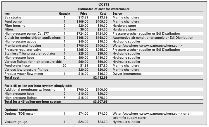
For about $2,500 you can build a 20-gallon-an-hour watermaker, and for less than $3,200 (the price of an off-the-shelf 3.5-gallon-per-hour unit) you can build a 45-gallon-an-hour watermaker. With the exception of the high-pressure pump (used in watermakers and pressure washers) and the membrane and pressure vessel, all the parts of the watermaker I built are used in many other industries.
As you build the system, you can separate the modular components and place them where they best fit your boat. Each installation presents challenges. Construction and placement of items such as brackets for mounting the high-pressure pump, hoses, and pre-filters, vary from boat to boat.
Basic concepts
Reverse-osmosis desalination systems, better known as RO watermakers, are easy to understand. Seawater has a salinity of about 10,500 to 14,000 parts per million (ppm) of total dissolved solids (tds). This means that for every one million parts of average sea water, there are 10,500 parts of various salts dissolved in it. To remove these salts, sea water is pumped against a membrane, then through a valve that restricts the water flow and creates a pressure of 800 pounds per square inch (psi) across the membrane.
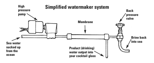
Some of the water is forced through the thin membrane, leaving its salt content behind. Between 10 and 20 percent of the water comes out the opposite side of the membrane as fresh water with less than 500 ppm total dissolved solids. The rest of the seawater, now with slightly more than 10,500 ppm tds, goes overboard. The membrane is analogous to a filter which removes salts from the water at high pressure. In its simplest form, a watermaker would look like the one in the illustration on Page 17.
By adding a few other components to the system, we can make the watermaker easier to operate and maintain.
Complete system
Most of the work is simple plumbing, running hoses from each component to the next. The hoses between the high-pressure pump and the membranes and between the membranes and the pressure-regulator valve, need to be high-pressure hoses, with a working pressure of at least 3,000 psi. Be careful when making these connections. High pressure can be dangerous if a sudden failure of a fitting or a hose occurs. Be safe, take the extra time to check each of the high-pressure fittings for correct installation before running the watermaker for the first time, or after a long layup. (There are several kinds of hydraulic fitting connections. It is possible for them to look like they will connect together but not actually connect together properly. Make sure that all of your fittings are of the same type, have the same number of threads per inch, and have the same taper —Ed.)
In plumbing the hoses, it is important that you not use Teflon tape on any of the fittings. It frequently comes apart inside the system, and can clog the membrane or even the pressure-regulation valve. Instead, use modest amounts of a thread-sealing compound. Be careful not to get any of it into the system. Most of these compounds are petrochemical-based and can damage the membrane. Never use thread sealant on SAE and JIC compression fittings.
The feed pump and the clutch, or motor, for the high-pressure pump will need to be wired into your electrical system. Use the correctly rated switches and fuses. If you are driving the high-pressure pump directly from the main engine, the clutch draws about 5 amps and should be fused appropriately. The label on the feed pump should list the required fuse size.
Complete unit
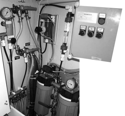
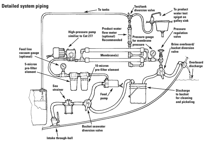
To get familiar with the components of a watermaker, follow the route the water takes as it is changed from sea water to drinking water. Refer to the drawing of a complete watermaker system on Page 18.
Intake through-hull: At least a 3⁄4-inch through-hull with a standard marine seacock or ball valve is needed to provide sea water to the watermaker. Install a dedicated through-hull for the watermaker, as sharing through-hulls with other on-board devices can lead to the early demise of the high-pressure pump through the introduction of air into the intake.
Feed water hose: A 3⁄4-inch, standard marine reinforced water hose works well for plumbing all components from the through-hull to the intake of the high-pressure pump. I have found Shields Series 162 polyester-reinforced clear PVC tubing to be perfect for this application. Your local chandlery should carry it for about $1.39 a foot.
Sea strainer: This is a simple sea strainer that keeps large particles out of the feed pump. Almost any sea strainer will work. A good choice is the Par 124297 or the Sherwood 391856, available from most chandlers.
Bucket/sea water diversion valve: A simple Y-valve will allow you to feed water into the system from a 5-gallon bucket or from the through-hull. This allows you to flush the watermaker with 5 gallons of the water it has produced after each use and to pickle and clean the watermaker when necessary.
Feed pump: The feed pump must have the same or higher throughput as the high-pressure pump. If you use a Cat model 277 for the high-pressure pump, a feed pump capable of at least 4 gallons per minute is necessary. There are several good choices of pumps available.
I used the Jabsco Water Puppy, Model 180810, in several installations. A better choice, requiring less maintenance, is the Jabsco Centri-Puppy, Model 356303. Since it is not self-priming, it must be mounted with the inlet below the waterline. Pick up a couple of spare impellers if you use the Water Puppy and are headed offshore. The feed pump should be on its own circuit so it can be turned on separately from the high-pressure pump. This allows the feed pump to bleed the air out of the system before initial startup and after changing the pre-filters. The switch for the high-pressure pump should be wired so the high-pressure pump cannot be operated without also turning on the feed pump.
Pre-filters: The pre-filter housing and filters can be purchased at a hardware store. These are the same units used in household sinks to eliminate sediment and odors. The more the filtration, the more the water flow is restricted and the larger the filter housing needs to be. Plan on filtering down to 5 or 10 microns. A 10- micron filter then a 5-micron filter works well. Filters are about $6.
Simple sediment filters of the wound-string type are all you require. Polyester-cloth elements are best. Paper ones tend to break down in sea water. Most oil and petroleum products float on the surface of the water above your intake and are not present in the feed water. If a harbor is so dirty that petroleum products float on the surface, I don’t run my watermaker.
If you plan to operate your unit in oily anchorages, make an oil/water separator out of an additional filter housing. Remove the filter element. Then either plug the upper outlet hole of the filter housing and drill and tap a standard 1⁄2-inch or 3⁄4-inch National Pipe Thread (NPT) fitting into the bottom of the filter housing, using the bottom fitting to draw the feed water out or cement a pickup tube into the center hole of the filter housing (the output fitting is connected to the center of the filter housing). If you make a pickup tube, get it as close to the bottom of the housing as possible without reducing the flow.
Optional vacuum gauge: A standard glycerin vacuum gauge is an optional, but good, investment. Placed between the pre-filters and the high-pressure pump, it can tell you when to clean or replace the pre-filter elements. These are available at most hydraulic hose and fitting suppliers. It must be glycerin-filled to dampen the effects of the high pressure pump’s piston strokes.
High-pressure pump: The high-pressure pump is a triple-plunger, positive-displacement pump. It pumps about 3 gallons of water per minute at 800 psi through the membrane. This is the heart of the watermaker system. The Cat Model 277 has a nickel-aluminum-bronze head; the Cat Model 271 has a stainless-steel head. While both are acceptable for use in RO watermaker systems, I have found the nickel-aluminum-bronze units to be a better choice. The 277 costs about $400 less and is less susceptible to anaerobic crevice corrosion and electrolysis than the 271. There are less expensive brands of pumps available, but others I’ve tried have fallen short of the dependability of Cat-brand pumps.
When filling the high-pressure pump crankcase with oil, fill it to the top of the sight glass not just to the center dot. When the glass is filled to the top, the pump will be correctly lubricated when the watermaker is running while the boat is heeled.
High-pressure hose: The high-pressure water between the high-pressure pump and the membrane and on to the pressure regulator requires high-pressure hose. This can be hydraulic marine steering hose, rated at 3,000 psi, or airbrake hose used on large trucks, rated at 3,000 psi. This gives you a 3-times safety factor. The hydraulic marine steering hose is more expensive and more subject to chafe, but it does not contain any metal, an advantage in limiting electrical conductivity and electrolysis. Any quality high-pressure hose will function, as long as it is water-rated and has a burst pressure of 3,000 psi or more.
Look in your phone book for hydraulic suppliers who can make the hoses to length for you, or purchase end fittings and cut the hose to length yourself. I recommend Parker Hannefin-brand hoses and end fittings. All fittings in the system must be bronze or (preferably) stainless steel. Rust from any mild-steel fitting will clog the membrane. I recommend reusable fittings, as they allow you to take along a single extra length of high-pressure hose — as long as the longest run in the system — for a spare. Should you develop a leak in a high-pressure hose, you can remove the reusable ends from the leaking hose and, using hand tools, install them on the spare hose no matter where you are. If you choose the air-brake hose, be careful where you run it; I have seen two boat fires that resulted when the air-brake hose chafed against wiring, and the steel braid in the hose shorted the chafed wires to ground.
A good way to measure how much high-pressure hose you are going to need is to run a standard garden hose through the route of the high-pressure hoses. Drill any necessary holes through bulkheads, etc. This gives you a good idea of the places where the high-pressure hose from the pump to the membrane will chafe. The fittings on the ends of the high pressure hose are about the same size as those on a garden hose, so this job demonstrates how easy or difficult it will be to run the hose.
The standard fittings for the ends of the high-pressure hoses are SAE compression fittings. These are standard on most hydraulic fittings in the U.S. The fittings on the high-pressure pump are 1⁄2-inch National Pipe Thread (NPT) on the intake, and 3⁄8-inch NPT on the output. The fittings on the membrane are generally 3⁄8-inch NPT. When you have your hoses made up, or go to purchase your hose and reusable end fittings from the hydraulic hose supplier, take your pump and pressure vessel with you to make sure that you purchase all the fittings to connect everything together the first time.
Chafe: Consider the problems of chafe in the high-pressure hose between the high-pressure pump and the membrane. This hose vibrates more than 5,000 times a minute, once for each stroke of the three pistons in the high-pressure pump. It will chafe on anything it rubs unless it is very firmly fixed in place where it contacts anything else. To avoid chafe and lengthen hose life, I feed the high-pressure hose inside a piece of standard reinforced marine water hose — Shields Series 162.
You can make a simple vibration dampener by coiling a section of high-pressure hose into three or four 12- inch diameter coils between the pump and the membrane. The hose that makes up these coils must be completely covered with standard water hose, or it will chafe on itself. It needs to be firmly attached at each end of the coiled portion, and the coils should be free-floating between the two attachment points. There are vibration dampeners available from Cat to solve this problem, but they are prohibitively expensive, and I have never seen one in use on a small-boat watermaker.
Membrane: What most people call a membrane is actually a combination of a membrane and the pressure vessel that encloses it. When purchasing your membrane, you must also purchase a pressure vessel for the membrane. The pressure vessels come in stainless steel and fiberglass. Fiberglass is the only choice for a seawater desalination system. Stainless steel is prone to crevice corrosion and electrolysis in this application.
There are three or four ports on a pressure vessel. They are: high-pressure water in; high-pressure water out; and product water out. Four-port vessels allow you to remove the product water from either end. The product water output opposite the one you choose must be plugged for the membrane to work correctly.
Membranes and housings are available from https://wateranywhere.com/. The most economical membranes and pressure vessels are the 2.5-inch by 40-inch ones. The membrane (SW30-2540) retails for $190 and the pressure vessel (PV2540) for $496. Also available are 21-inch long by 2.5-inch diameter membranes and housings. To achieve 20 gallons per hour, you would have to use two of these membranes plumbed in parallel to achieve the same output as one 40- inch membrane.
Membranes are long, and finding a place for them may be a problem on smaller boats. One of my favorite installations is to mount the membrane under the floor of the cockpit. This space is rarely used for other purposes and is perfect for the 40-inch membranes. The membrane can be mounted vertically or horizontally. Other installation ideas that work well are: inside hanging lockers; behind settees; under settee bottoms; inside
cockpit coamings; and in a corner of
the head compartment.
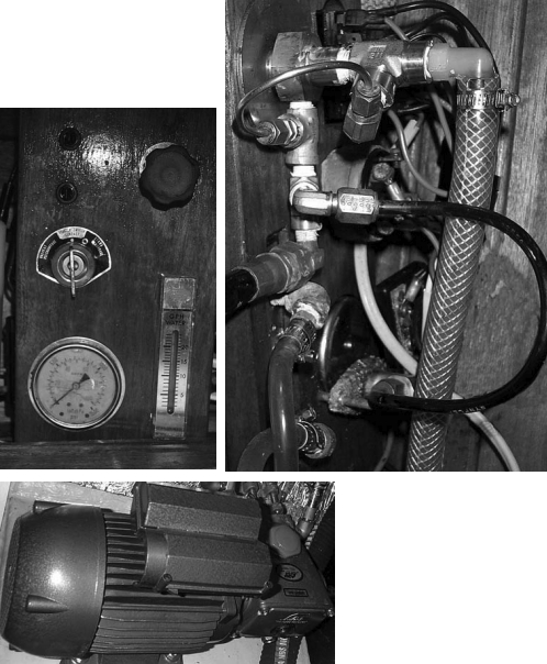
Pressure gauge: You need a standard glycerin-filled pressure gauge measuring up to 1,500 psi and rated for corrosive liquids use. This is placed off a tee fitting just before the regulation valve, so you can adjust the pressure, using the gauge. The line going to the gauge must be pressure-rated for at least 3,000 pounds under working conditions, as are all the components between the high-pressure pump and the back-pressure control valve.
Use stainless or specialized plastic tubing for the run between the tee and the pressure gauge, as this makes for easy panel placement and a minimum of bulky high-pressure hoses on the rear of the panel. The tees and the tubing should be available from the same local hydraulic supply house where you purchase your high-pressure hoses and fittings.
Regulation valve: Cat produces an excellent valve for this purpose, backpressure valve Model #7070. It is available from Edi Distribution.
Overboard hose connection: Once past the back-pressure regulation valve, the water is no longer at high pressure, although it still is flowing at 3 gallons per minute. Standard marine water hose from the output of the regulator valve to the overboard discharge is fine. This hose should be 3⁄4-inch to handle the flow.
Install a simple plastic Y-valve between the output of the back-pressure regulator valve and the overboard through-hull to pickle and clean the membrane. One side of the valve connects via a hose to the brine overboard discharge through-hull. The other side has a hose barb for fitting a hose long enough to reach a 5-gallon bucket near the bucket/seawater intake diversion valve for use in cycling, cleaning, and pickling solutions through the watermaker.
Brine overboard through-hull: The overboard through-hull must be installed above the waterline. This is where the brine is discharged from the watermaker. Remember it’s going to put out 3 gallons a minute, so place it where it won’t flood your dinghy.
Product water hose: Product water from the membranes is carried through the flow meter and selector valve to the tanks via standard 3⁄8-inch marine reinforced water hose. The product water output should not be restricted while the unit is running. If it is plugged or restricted, damage can result to the membrane.
Product water flow meter: The product water flow meter indicates how much fresh water the watermaker is producing. It makes sure that everything is working correctly and helps indicate when to clean the membranes. The most easily read model is made by Dwyer. It is a stainless-steel ball inside a clear plastic tube. As water goes around the ball, it is lifted in the tube. Product water from the end of the membrane comes into the bottom of the flow meter and out of the top to the tank/test diversion valve.
Tank/test diversion valve: This is a simple Y-valve. Plastic is perfect for this low-pressure product water output use. In the sample position the product water flows via a standard sink spout into the sink or into a cup for testing. Once the water tastes good, or (if you are using a tester) contains less than about 500 ppm tds, turn the valve and start filling your tanks. You may want to add a couple of other valves to select which tank to divert the water into. Or as one customer requested: “Just make it go to a hose, so I can fill anything I want.” This avoided running a lot of plumbing inside his small boat. When he wanted to fill his tanks, he ran a hose to the deck fills.
Powering the pump
The high-pressure pump can be driven in a number of ways; each method has advantages and disadvantages. The most common way to drive the high-pressure pumps on larger watermakers is directly off the engine. The high-pressure pump can also be driven with a 120-volt AC electric motor.
Engine-driven pumps
Driving the high-pressure pump with the main propulsion engine has the advantage of ease of installation and simplicity; it requires only a couple of pulleys and a belt. Its only disadvantage is that it requires the main engine to be operating to make water. If you regularly use your main engine to charge your batteries, this is a good option. Your batteries charge, and you make water at the same time. It is also a good option if you generally motor in clean water. On most small cruising boats without a generator, this is the most effective option.
A pulley must be available on the front of the engine to drive the high-pressure pump from the main engine. This may necessitate the addition of a pulley, or PTO unit. The Cat 277 pump uses about 2.5 horsepower, so a single drive belt is sufficient to drive it. Calculate the size of the pulley necessary on the pump so that at cruising speed the pump is turning not more than 1,725 rpm. Between 750 rpm and 1,700 rpm is ideal.
Most installations use a 6-inch pulley on the main engine and a 7-inch electric clutch/pulley on the high-pressure pump. This allows the watermaker to operate when the engine is rotating between 800 rpm and 2,000 rpm. If your engine pulley is a different size or your cruising range is outside of these numbers, you’ll need to do a little math to find the correct size to put on the high-pressure pump.
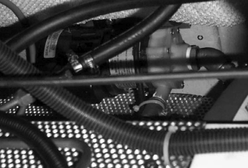
A 12-volt electrical clutch exactly like that found on automotive air conditioners is placed on the shaft of the high-pressure pump. A standard 7-inch clutch sheave unit is available from Edi Distribution, or may be found at your local refrigeration and air-conditioning supplier. Take your pump with you to check fit. The pump shaft is 0.650 inch and is straight, not tapered.
You will need to fabricate a system to fit the high-pressure pump to the engine and allow for adjusting belt tension. Most of these are simply two metal plates hinged together at one end, with the angle between the plates adjustable with two bolts threaded into the top plate. The bottom plate is mounted to the top of the engine, and the high-pressure pump to the top plate. Other bracket mountings can be used, including mounting the high-pressure pump next to the engine on soft mounts such as those used to mount transmissions in cars. These mounts are then attached to a plate, with a slot cut near each corner allowing the plate to slide toward or away from the engine, allowing you to tighten the belt. Make sure your pulleys are aligned to prevent excessive belt wear and to ensure that people cannot accidentally get caught in the moving parts.
120- or 240-volt AC pumps
Driving the high-pressure pump with a 120- or 240-volt AC motor is a good solution if your boat is equipped with a generator. It allows you to place the electric motor/high-pressure pump anywhere in the boat with a minimum of wiring. Small-frame 120- or 240-volt electric motors are available cheaply and are easily fixed all over the world. While running the generator for other needs, such as battery charging or cooking, switch on the watermaker. The only disadvantage is that your ability to make water depends on your generator being operational.
It is also possible to drive the high-pressure pump motor from the output of a sufficiently sized inverter. This sometimes allows the watermaker to be operated while the main propulsion engine, is running without its having the high-pressure pump mounted directly to the engine. This can be an attractive solution if you want to run the watermaker regardless of what source is charging the batteries and if you already have an inverter large enough to drive a 2-horsepower, 120-volt motor. The disadvantage is that your ability to make water depends on your inverter working.
A small-frame, 2-horsepower, 120-or 240-volt motor turning at about 1,100 rpm can be directly coupled to the shaft of the high-pressure pump using a flexible coupling. The best source for these is a local electrical supply house. Motors with a different rotational speed can be attached to high-pressure pumps by placing both the motor and the pump on a plate and driving the pump with a belt-and-pulley arrangement. A slightly more expensive, but easier, option is to order your high-pressure pump from your dealer with a 120-volt AC motor already coupled to it.
Operating the watermaker
Make sure the through-hulls are open and the bucket/seawater diverter valve on the feed pump input is set to seawater position, the sample/tank diverter valve is in the sample position, and the bucket/overboard diverter valve on the brine output is in the overboard position.
The high-pressure pump should not be operated without the feed pump running. Doing so could cause cavitation and damage to the high-pressure pump. Never operate the high-pressure pump if it is drawing a vacuum on its input or if there is air in the system. Filling the pre-filter units with chlorine-free water before using the unit decreases the time necessary to eliminate air from the system.
The first time you run the watermaker, expect to spend several minutes eliminating air from the system. On subsequent startups, it will take only a few seconds to make sure there is no air in the system. Make sure the pressure regulator is in the fully out position; pressure at startup should always be zero.
Turn on the feed pump without turning on the high-pressure pump. Watch the brine output until it’s free from air and runs in a constant stream. Start the high-pressure pump.
If the needle on the pressure gauge jumps rapidly up and down, it generally indicates that you have not bled all air from the system. Turn off the high-pressure pump, leaving the feed pump on for a few more minutes, then try again. Continued erratic movement of the pressure gauge may indicate the need to shut down the system and check for leaks.
One of the most common sources of leaks is the gasket on the pre-filter canisters. Once the system is free of all air and the high-pressure pump is running, slowly turn up the pressure regulator until the pressure gauge reads 800 psi.
Product water should be produced in about a minute, and within five minutes the watermaker should be producing product water at about 18 to 22 gallons an hour, or about 35 to 40 gallons an hour if you installed two membranes.
As the membranes are originally pickled with formaldehyde at the factory, run the watermaker for about 40 minutes before testing or switching to the tanks the first time it’s used. Once the unit has run for about 40 minutes, check the product water using a TDS meter or by tasting it. In normal operation, run the watermaker for about 10 minutes before testing the product water.
To shut the unit down, fill a bucket with product water from the watermaker, then slowly decrease the pressure. When the pressure is at zero, turn the high-pressure pump off, then turn off the feed pump. Switch the seawater/bucket diverter valve to bucket, and place the input hose in the bucket. With the pressure-regulator valve in the out position, turn on the feed pump and the high-pressure pump. Turn off both pumps when you have about 4 inches of water left in the bucket.
Always remember to turn the high-pressure pump off and then the feed pump. Close all through-hulls. Flushing the unit with fresh water after each use will increase the life of the membrane, and the time between membrane cleanings. The extra 15 minutes of running the watermaker to make 5 gallons of water for flushing the unit after each use will greatly increase the life of all of the components of the watermaker.
Maintenance
Always flush with fresh product water after making water. Water that enters the system must be free of chlorine. Use a standard pool chlorine test kit, available from your local pool supplier for less than $5. Any chlorine in the water going through the membrane can severely damage it.
Clean the pre-filters if the vacuum gauge shows a vacuum on the supply side of the high-pressure pump or after about 8 hours of normal use, more frequently if the watermaker runs in water with heavy sediment. Generally, you can clean the cloth-type filter elements about eight times before they wear out. To clean them, flush clean water backward through them. Replace them when you can no longer get them clean, or they lose their rigidity.
Pickling the system
Pickle your system if you are going to leave it without running for more than two weeks. After every 100 hours of use, change the oil in the high-pressure pump. Use Sta Lube 2553, the same oil as the Cat pump oil but at less than 20 percent of the cost. Look in the phone book for Sta Lube.
To pickle or preserve the membrane, the pressure vessel is filled with a biocide that keeps organisms from growing on and in the membrane. Growth on the inside of the membrane is very difficult to remove, reduces water production, and can cause an unpleasant sulfur smell in the product water. This is the most common reason for membrane failure.
The pickling solution is sodium metabisulfite. It is used as antiseptic for brewing and can frequently be found in the brew-your-own stores as well as local chemical supply houses. The local chemical supply house is the cheapest supplier. Look up “chemicals” in your phone book.
Make sure that you use the pickling and cleaning chemicals with good ventilation. They can produce noxious fumes. Remove the pre-filter elements from the pre-filter vessels, fill the pre-filter vessels with non-chlorinated reverse-osmosis (RO) water, and screw back into place.
Mix 6 tablespoons of sodium metabisulfite with 3 gallons of water in your 5- gallon bucket. With the system off, connect the flush-and-pickle hose to the intake selector valve. Turn the valve to flush-and-pickle, and place the other end of the hose in the bucket. Connect the other flush-and-pickle hose to the brine-output selector valve and turn the valve to the bucket position.
Place the other end of the hose in the bucket. Run the system under no pressure, with the sodium metabisulfite solution circulating for about 10 minutes. Shut down the unit, and close all valves. The membrane should be repickled about once every 90 days when not in use. Before you use the watermaker again, replace the pre-filter elements, and run the system for at least 40 minutes before testing or switching the water to the tank position.
Cleaning the membrane
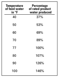
The membrane should be cleaned only when the product output drops by 15 to 20 percent. Account for temperature effects on product-water output before deciding that you need to clean the membrane.
There are two varieties of cleaners. One is an aggressive alkaline phosphate detergent, which removes grime, slime, oil, and grease. The other is an acid, which removes scale, rust, and mineral deposits. With correct flushing and by avoiding running the watermaker in polluted harbors, it is rarely necessary to clean the membranes. Most cruisers clean their membranes less than once a year.
The chemicals are produced by a variety of manufacturers, although finding them in quantities of less than 25 pounds can be a problem. For ease of purchase and use, purchase the chemicals from one of the commercial watermaker companies or off the shelf at a chandlery. If you want to buy a big bag of either, the chemicals are listed, including available brand names, in the ROSA technical manual produced by Dow Chemical’s membrane division.
ROSA is available for free. It is an excellent source of information on flow rates and membrane maintenance, and it has some tips for designing systems. ROSA is an extremely technical document, created by the people who manufacture all types of RO membranes. While it answers most questions, you may have to do some research to understand the answer.
To start the process, mix 10 tablespoons of either the alkaline or the acidic chemical solutions with 3 gallons of water and follow the same procedure as for pickling, except that you must allow the solution to circulate without pressure for 20 minutes.
After each cleaning, the watermaker must be run for at least 20 minutes before cleaning with the other solution or testing product water. Under no circumstances should either cleaning solution be left in the system more than 20 minutes.
All three of the chemicals used in cleaning and pickling the watermaker are toxic and should be disposed of after use in an approved manner. Dumping a bucket of phosphates or diluted acid overboard could land you in serious trouble with the EPA.
Testing the water
A portable TDS meter can be used to test the quality of the product water. I recommend the Oakton TDS Testr available at most chemical supply houses, or a Hanna 1 tester, available from http://www.wateranywhere.com.
The easiest way to decide if the product water meets your standards is to taste it. Humans can generally taste about 1,200 ppm total dissolved sodium in water. The World Health Organization recommends less than 500 ppm tds in water for human consumption. Most watermakers in cruising waters produce water with less than 250 ppm tds, which is less than most shoreside municipal water systems.
Temperature and salinity
The warmer the water, the more product water will be produced, although it will have slightly more salinity. In areas with warm, high-salinity sea water, such as the Sea of Cortez, you may get tds readings up to 350 ppm. This water is still fine for consumption. You won’t taste any difference. Don’t operate your watermaker in water warmer than 100°F. Damage to the membrane will result.
The colder the water, the less product water is produced. For example, using the following table, assume we operate a watermaker rated at 20 gph at 77°F (the standard temperature for membrane-output rating) and that we are floating in 50°F water.
Under these conditions, we can expect to produce about 10.6 gallons per hour. (Fifty-three percent of 20gph is 10.6 gph.) We can also expect the salinity of the product water to go down slightly.
Perhaps the best thing about building your own watermaker is drinking a glass in a far-off port, without having to worry about how much water you have used, where to jug it from, or if you are going to get sick from drinking it.
Thank you to Sailrite Enterprises, Inc., for providing free access to back issues of Good Old Boat through intellectual property rights. Sailrite.com