A really thorough job: Even the deck was removed
Issue 53 : Mar/Apr 2007
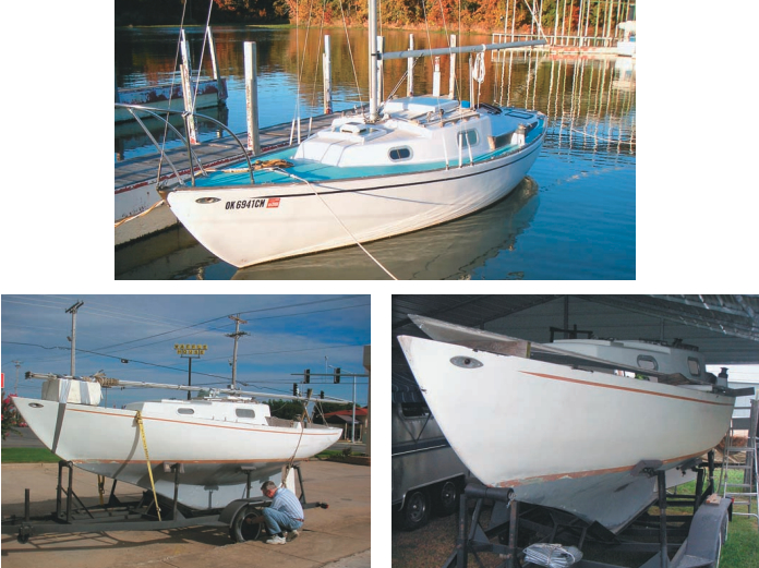
While work was stalled on my 1969 Kenner Kittiwake project boat, I learned of a newer Kittiwake being auctioned on eBay. I was intrigued and, since my wife had shown interest in getting a boat for our niece and nephew, I placed a bid and was the successful bidder. It was just 230 miles from our home and a tandem-axle trailer was included with the boat. Another attraction was that it had an inboard engine. This was, in fact, the only Kittiwake ever built with a factory-installed inboard engine. This boat, hull #538, was built in 1978 by River City Sailcraft.
In the mid-1960s, Kenner Boat Company in Knoxville, Arkansas, was building the South Coast 23, a Carl Alberg design, for the South Coast Boat Company. For reasons that are not clear (and possibly not forthright) the South Coast people took the molds and moved to Louisiana. Left without a mold, the Kenner people modified a hull and deck that had been stored offsite by increasing the overall length by 7 inches and the beam by 2 inches. They added a 2-inch step to the aft part of the trunk cabin and relocated the outboard well from the cockpit to the port side of the lazarette. They used the modified hull and deck as plugs to make new molds, and the Kittiwake 23 was born.
There have been three builders of the Kittiwake 23: Kenner Boat Company, Ray Greene and Company, and River City Sailcraft. The total number of Kitti wakes produced is unknown, as records from Kenner and Ray Greene are not available. Kenner built approximately 300 boats, Ray Greene probably built fewer than 50, and River City Sailcraft built 69 boats. The construction period spanned from 1966 through 1978.
For personal use
The person auctioning the boat that caught my eye had intended to refit it for use as his personal sailboat. There was evidence of a hull-to-deck-joint leak along the starboard side, aft of the main bulkhead. There were no associated rot issues with the leak. He had removed the teak toerail, separated the deck from the hull, and removed the engine. Then other things in life had become priorities for him, and the boat collected dust in his shop for a year.
When my wife and I went to pick it up, we found that it came with four North sails. The mast had internal halyards led back to the cockpit, the genoa winches were two-speed Barients, and there were single-speed Barients on the cabintop for the working jib and halyard tensioning. Because of the uniqueness of this Kittiwake, when I saw it I decided to renovate it for my own use and let our niece and nephew have my 1969 Kenner boat instead.
In spite of the disassembly that had been done, this boat appeared to be in good shape. All items necessary for putting it back together appeared to be there. Later I learned that a bit of the teak toerail and some of the engine-exhaust piping were missing, but these were minor items.
I parked the boat under a carport. With the help of hydraulic jacks, I raised the deck and cribbed it with 4-inch timbers. I began removing the silicone sealant from all surfaces of the hull-to-deck joint. Once I had mechanically removed all of the silicone sealant, I sanded all the joint surfaces. Next I washed these surfaces first with xylene solvent then with acetone. I hoped to eliminate all silicone sealant residue so the 3M 5200 sealant I planned to use would bond well.
I enlisted a friend to help put the hull and deck back together. We each took a caulking gun and applied 5200 liberally to the hull flange. Then my wife and my friend pushed screwdrivers through the bolt holes to hold the proper alignment as I lowered the deck to the hull. This worked well; all the bolt holes lined up nicely. We installed the bolts and pulled them up just enough to begin squeezing out the sealant and to check for gaps showing daylight. I let the 5200 sealant cure, undisturbed, for a couple of days.
Mast compression beam
The compression beam for the deck-stepped mast was cracked in the middle beneath the mast. The builder had put one through-bolt exactly in the center of the beam and the trim piece beneath the beam had been attached by #8 1-inch wood screws. A couple of these screws were driven into the beam at the midpoint of the span. The original owner of the boat had drilled a notch in the top edge of the beam near its center, further weakening it. These factors combined to make the beam weakest at the point of greatest load. The beam consisted of two pieces of 3- x 3⁄4-inch mahogany cut to fit the overhead, spanning from port to starboard.
I cut two new beam pieces from 3⁄4-inch red oak. (Note: white oak is a better choice for boat projects. –Eds.) The old beam pieces were used as a pattern for the upper arc, but the lower arc was flattened to make the depth of the beam about 3⁄4-inch greater at its midpoint. The new beams were mounted with four bolts instead of five and the trim pieces were reinstalled with the mounting screws carefully located to avoid weakening the center of the deck beam. Then I reinstalled the rest of the main bulkhead trim pieces and the compression posts.
Electrical work
All the wiring had been stripped out of the boat. Fortunately, the documentation I received included a very good engine-wiring diagram. I also had a cabin-wiring diagram from my first Kittiwake. I wanted to add a depth sounder, GPS, radio/cassette player, automatic bilge pump with float switch, and a 30-amp shorepower receptacle. The boat came with running lights for the bow and stern and the original five-switch panel with fuses but no steaming light on the mast. It also had a lighted compass that had never been hooked up.
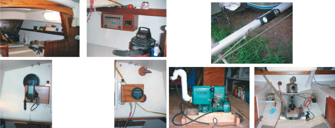
I added a switch panel to provide switches for the GPS, depth sounder, instrument lights, and the radio/cassette player. It also houses the separate manual/off/auto switch for the bilge pump. I made mounting brackets for the GPS and depth sounder that allow the instruments to swing out into the companionway for viewing while sailing. In the Porta Potti compartment, I mounted a battery master switch that will allow for the future installation of a second battery. I bought a combination steaming/deck light to install on the mast.
Engine
The engine is a single-cylinder, two-stroke gasoline marine engine made in Finland, called a Vire 7, that had been marketed in the United States by the Westerbeke company. It is a pretty interesting little engine, but parts are getting hard to find. It has a discussion group on the Internet at . It has a transmission with forward, neutral, and reverse. The single-lever throttle and shift control was still mounted in the cockpit. The ignition switch panel, with blower switch and kill switch, was mounted in a panel at the aft end of the cockpit. I did not get a key for the ignition switch. A local locksmith was able to cut a new key for me.
The engine-cooling water pump was reported to be a problem area by the Vire discussion list participants. The pump is driven by an accessory shaft from the transmission. It is mounted very low on the aft end of the transmission. It is very small and, with the engine installed in the boat, it is almost impossible to see and even more impossible to work on. I decided to install a separate water pump, driven by a 12-volt DC motor. I mounted this pump near the engine in the engine compartment, which fortunately is quite roomy compared to some I’ve encountered on much larger boats. I wired this pump to the ignition switch through a solenoid so the pump is only powered when the ignition switch is on.
The Vire 7 engine has a belt-driven generator that also acts as the starter. The engine is fired by a magneto. Once the engine starts up, the ignition switch can be left in the accessory position to provide 12-volt power for other equipment. The accessory position provides power for the engine-cooling water pump I installed. To shut the engine down, a push-pull switch on the engine control panel is pulled out to ground the magneto. Turning the ignition switch to the off position will not kill the engine.
Filled the silencer
One thing I learned after getting the boat in the water was that the ignition switch needed to be turned to the off position just before pulling out the kill switch. The first time I ran the engine after launching the boat, I failed to do this. The cooling water pump continued to run. This filled up the Hydra-hush exhaust silencer and allowed water to feed back into the engine exhaust pipe and fill the engine cylinder with water. Fortunately, a two-stroke engine is pretty easy to clear and no permanent harm was done. To prevent this from happening again, I have replaced the original push-pull switch with a new one that breaks the circuit to the cooling water pump when it is pulled out to kill the engine.
I wanted to check out the operation of the engine before attempting to reinstall it in the boat. At first, it would not run, but after I rebuilt the magneto and carburetor, it fired up and spun like a top. I hoisted the engine aboard, moved it back onto its mounts, and bolted it down.
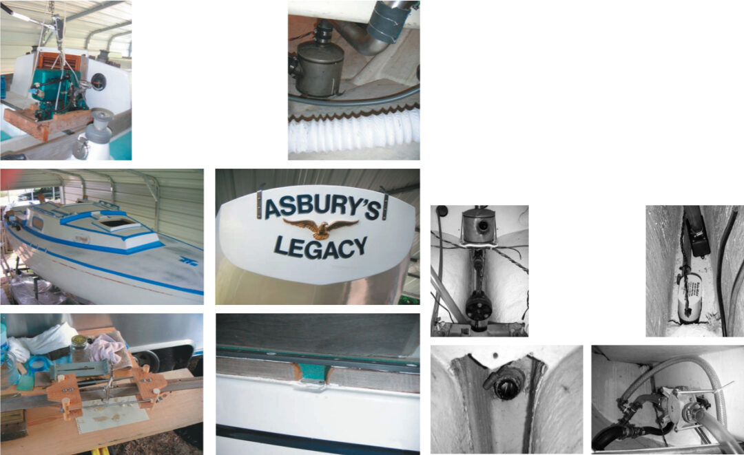
With the engine in place, I determined that the location I had selected for the Hydra-hush exhaust silencer would not work. The silencer had to be relocated behind the aft bulkhead in the main cabin on a small flat area at the end of the keel. The exhaust hook-up was completed from the engine to the silencer and from the silencer to the exhaust port through-hull using exhaust hose and pieces of stainless-steel exhaust pipe.
The throttle and shifter cables were already connected to the Morse control unit mounted in the cockpit. These cables were routed to the appropriate locations at the engine and connected to their respective devices. The ignition switch panel in the cockpit had a convenient hole that I used to mount a manual choke control, purchased from a local truck parts supply house.
Painting
Once the majority of the wiring was done, the weather warmed up enough that I could begin refinishing the boat’s exterior. The previous owner had sanded and repaired the bottom. I had learned of a paint that was developed for use on the underwater portion of offshore oil rigs.
This epoxy paint has an extremely high solids content composed of minute ceramic particles. It has a very high adhesion and is quite flexible. It is so slick that marine organisms are supposed to have a difficult time bonding to its surface.
I decided to use this paint as a barrier coat below the waterline. I did not apply any antifouling bottom paint, in order to test the surface slickness properties. At this point, the success or failure of this experiment has yet to be established.
I filled blemishes in the topsides with gray Marine-Tex epoxy putty and sanded them fair. The hull and deck were then prepped and primed with Interlux Multithane 2100. I painted the topsides and the smooth portions of the deck with two coats of Interlux 2359/2314 Interthane Plus White. Neither of these products provided the brushmark-free finish that the manufacturer claimed, even though I followed the application instructions closely. I applied a contrasting dark blue waterline stripe with Interlux 4990 Brightside boot top paint.
Next I applied Durabak 18 to the non-skid areas of the deck. This product was featured in an article in the September 2004 issue of Good Old Boat. The Durabak product is providing an excellent non-skid surface and shows no wear. I found a name graphic and vinyl tape for the cove stripe and an eagle relief with which to adorn the transom.
The interior of the boat was in pretty good shape. I cleaned it up and painted the inside of the hull and the berth surfaces with Interlux Brightside one-part polyurethane white paint.
Toerail
Once all painting was completed, reinstallation of the teak toerail began. The toerail had been broken in several places during its removal. I removed the loose splinters, cleaned the breaks with acetone, coated the broken ends with Gorilla Glue polyurethane adhesive, and aligned and pushed the pieces together. I fabricated a jig to pull the broken ends tightly together. Once the glueup was complete, the jagged ends worked like finger joints and the repairs are almost unnoticeable.
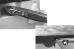
Kittiwakes have two molded-in depressions at the low point of the sheer on each side. These are supposed to act as scuppers to drain water from the deck. The toerail forms a continuous bridge above these depressions. However, the small opening gets clogged, reducing the flow through the scuppers. I elected to cut the toerail at these scuppers (photo on Page 12). This has been a satisfactory solution.
The pieces of toerail that were missing when I picked up the boat were about 6 feet long. They were supposed to be mounted at the aft end along each side. The piece of toerail that goes across the stern was also missing. I made a template in the necessary shape and cut new pieces. All pieces of the toerail were primed with BoatLife Lifecaulk Primer and bedded with a liberal amount of BoatLife Lifecaulk polysulfide sealant. I wish I could say that this was 100-percent successful, but there is still a slight leak along the starboard side aft of the main bulkhead. I’m developing a plan to attack and correct this problem.
Miscellaneous
The old Cutless bearing for the propeller shaft needed to be replaced. I ordered a properly sized new bearing. There were no retaining screws holding the old bearing in the hull tube. I had to cut it lengthwise in three places with a bare hacksaw blade. Once these very careful cuts were completed, I was able to pry the three segments of the bearing out of the tube. The outside surface of the bronze tube of the old bearing had been scored, coated with an epoxy paste, and pushed up into the hull tube, where it hardened in place. The old epoxy left ridges in the hull tube that had to be removed to allow the new bearing to be pushed into the tube. The new bearing was scored, coated with epoxy, and installed in the same manner as the old bearing had been.
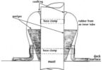
The inboard end of the prop shaft tube provides the attachment point for the piece of hose that houses the propeller-shaft packing gland. There was only room enough for one hose clamp to secure this hose to the tube. I was uncomfortable with this situation so I built out some additional length to this tube using epoxy and fiberglass tape. This has enabled the use of double hose clamps on the packing-gland hose.
I purchased new Teflon-coated packing, cut and installed it in the packing gland, and applied packing lubricant to the packing prior to the reinstallation of the prop shaft.
There were some small cracks in the rudder along the lower leading edge. I ground them out with a Dremel tool and filled them with Marine Tex. I sanded the Marine Tex fair and applied a couple of layers of fiberglass cloth to reinforce the whole cracked area. This reinforced area was also sanded fair.
Rebedded deck hardware
Using liberal amounts of Boat Life Liquid Life Caulk, I rebedded deck hardware that had been removed. Liquid Life Caulk is a polysulfide bedding compound that remains flexible when cured and can be removed if the hardware needs to be replaced in the future. I made a new teak spacer block to go between the mast step and the deck. The deck had three sets of holes where the mast step had been repositioned at various times. I plugged these holes with epoxy-coated hardwood dowel rods. Then I drilled four new holes to secure the hinged mast step to the deck. I bedded the mast step and teak spacer block with Life Caulk and bolted them to the deck. It is important to apply Life Caulk primer to teak components to ensure that the Life Caulk will adhere to the oily teak.
The acrylic in all the portlights was crazed and one of the pieces was cracked from top to bottom. I removed the entire frame of the cracked portlight only to learn that this was not a good thing to do, as the aluminum frame had been bonded to the hull very securely with silicone sealant. I created a significant cleanup problem for myself because silicone sealant is the preferred material for bonding the aluminum frame to the fiberglass, but fresh silicone sealant bonds very poorly, if at all, to old silicone sealant. I had to very diligently clean all the old sealant from the fiberglass and the frame and then wash everything down, first with xylene solvent and then with acetone, with the hope of removing all the silicone residue.
The acrylic was easily removed from the frame by first removing a plastic retaining trim ring and then pushing the glass out of the frame. A soft, very pliable and sticky sealant provided the watertight seal between the acrylic and the aluminum frame. I removed the trim rings and popped out the panes from the other three portlight frames. The trim rings had shrunk and hardened and were very brittle.
Scrap polycarbonate
I cleaned all the old sealant from the frame flanges where the panes mounted. I obtained a piece of scrap polycarbonate from a plastics supply house. This polycarbonate had a very light smoke tint. The new pieces for the portlights were marked up for cutting by using the old portlights as templates. Cutting was done on a bandsaw and then the edges were smoothed with a belt sander. A sealant material called Putty Tape is sold by RV parts houses. This appears to be the same sealant that was used between the aluminum frame and the acrylic before. This is what I used to bed the new polycarbonate pieces into the frames. I used window screen gasket tubing in place of the old hard trim rings and applied a bead of silicone sealant all around the joint between the frame and the polycarbonate on the outside.
The boat came with a manual bilge pump that was mounted so that it could be operated in the cockpit. I added an electric bilge pump with an automatic switch to take care of the water that accumulates from the occasional drip from the packing gland. The electric bilge pump is connected directly to the battery via a manual/off/auto switch and fuse. I also mounted a solar panel on the port side lazarette hatch cover to keep the battery topped off. New hoses were run from the cockpit scuppers to the drain through-hulls. All hoses to through-hulls are double clamped using stainless-steel hose clamps.
The sails were in good condition. Only the mainsail needed some minor repairs. This work was done by a sailmaker.
The only rot I found in the boat was in the knee beneath the deck at the transom. This knee is the attachment point for the backstay chainplate. I removed the chainplate and poured a liberal amount of GitRot into the knee. I had decided that I wanted an adjustable backstay, so I fabricated two new backstay chainplates and mounted them on each side of the transom. I shortened the original backstay and rigged up a split backstay with tensioner.
I launched the boat in September of 2005 at Applegate Cove on the Robert S. Kerr Reservoir on the Arkansas River. I was able to enjoy several beautiful fall sailing days. The boat sails beautifully . . . just as a Kittiwake should.
Thank you to Sailrite Enterprises, Inc., for providing free access to back issues of Good Old Boat through intellectual property rights. Sailrite.com