In “Mounting the Outboard Inboard, Part 1,” September 2018, James Baldwin summarized the pluses and minuses of replacing an inboard engine with an outboard motor, and specifically the benefits of installing the motor in a well that allows it to be tilted up and out of the water when not in use. In Part 2 of the article, he describes how he built such a well in an Alberg 30.
Fitting a well for a 9.8-horsepower motor in an Alberg 30
Issue 123: Nov/Dec 2018
It’s a common scenario: the original gas or diesel inboard engine on an otherwise usable older sailboat gives up the ghost, and the owner walks away. This is understandable, considering the cost of installing a new engine often exceeds the value of the boat. Sadly, many of these abandoned boats end up in landfills. Some of them, though, could present opportunities for cash-strapped but enterprising sailors who see the merits of repowering with an outboard motor. Fitting that motor in a well eliminates some of the drawbacks of hanging it on a transom bracket, where it’s unsightly, difficult to operate from the cockpit, and vulnerable to being dunked in waves or rising up until the prop sucks air.
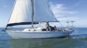
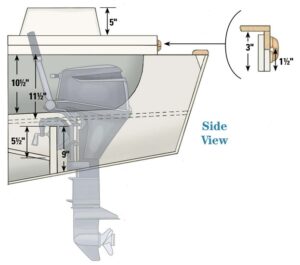
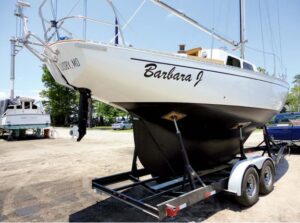
Certain design elements — keel-hung rudder, overhanging stern, and a large lazarette locker that’s a minimum of 30 inches between the transom and the cockpit’s aft bulkhead — make a boat a good candidate for conversion to an inboard outboard that can be tilted up and out of the water. An ideal example is the Alberg 30, a classic offshore-capable Carl Alberg design that remains plentiful on the used-boat market. I have installed 6-horsepower motors on both early- and late-model Alberg 30s. Here, I describe building a well for a 9.8-horsepower motor with an extra-long shaft in a 1968 model named Barbara J. Even though the bigger motor adds another 35 pounds and somewhat complicates the construction, many sailors prefer the extra power it provides for motoring through more adverse conditions.
I completed this project, with much-appreciated assistance from my wife, Mei, while the boat sat on a trailer behind our house. Most of the work could be done on a boat in the water, after shifting weight forward to raise the waterline at the stern a safe distance for cutting through the hull, but at some point the boat must be hauled for removing the prop and closing off its aperture.
First steps
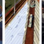
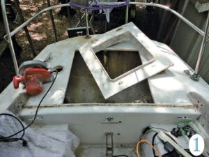
Before doing anything else, I removed the broken Atomic 4 gas inboard engine and its accessories. I then began the conversion by cutting the lazarette hatch opening to 26 × 31¼ inches using a circular saw and a Sawzall, saving the original hatch hinges for reuse (photo 1). With the improved access, I removed all the hardware fastened to the afterdeck, including the mainsheet traveler and backstay chainplate. This was also the right time to replace the original 6-inch mooring cleats with 10-inch Herreshoff cleats.
I cut out the chainplate knee with a Sawzall and a metal cutting disc on an angle grinder and then ground all the inside surfaces with a 36-grit pad on the angle grinder. At this point, I patched the forward lazarette bulkhead with plywood and fiberglass where needed to make it watertight from the bilge and side cockpit lockers. This ensures that, in heavy weather, water will not enter other areas of the boat from the free-flooding area of the well.
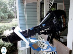
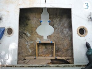
Needing a precise location and shape for the slot in the hull and transom for the motor’s midsection and shaft to pass through and then tilt up out of the water, I clamped the motor to our porch rail and, using wood, cardboard, plastic panels, and duct tape, built a mock-up of the hull and transom around it (photo 2). By tilting the motor up and down and swiveling it side to side, I was able to simulate the correct slot shape in the hull and transom, transfer that shape to construction paper, and lay the paper pattern against the hull’s centerline to mark for cutting (photo 3). From the mock-up, I determined that the forward end of the hull hole should be 16 inches aft of the lazarette bulkhead. Cutting the thick fiberglass was tough work, but I was able to get through it with the angle grinder and Sawzall.
To check the fit of the motor in the boat, I built a temporary jig out of plywood, lumber, and short pieces of aluminum angle screwed into the hull and cockpit bulkhead, and made some final trimming of the slot so that the motor could swivel and tilt up. I’ve found from building and using outboard wells on similar boats that the best compromise is to keep the prop well below the waterline but to not have the motor head too close to the water. This I achieved by making the height of the jig 8½ inches.
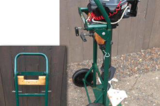
At close to 100 pounds, a 9.8-horsepower motor is awkward even for two people to wrestle in and out of the well. We used a boom-vang tackle to take the weight. On a boat that’s in the water, I extend the boom by lashing the whisker pole to it and attach the vang under that. Removing the prop makes it easier to insert the motor into the well and through the hull aperture. The prop can be reattached by tilting the motor up and leaning over the transom.
Putting it all together
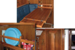
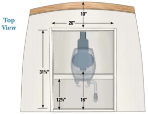
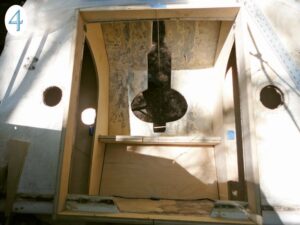
With the motor in place to provide a reference for clearance, I made cardboard patterns of the two longitudinal bulkheads and traced them onto ½-inch plywood. Set 26 inches apart to clear the motor when turned for side thrust, these panels serve as the inboard sides of the sealed lockers the two portable gas tanks sit on. I secured the panels in place temporarily with short screws driven partway into the hull and cockpit bulkhead (photo 4).
After removing the motor to make space to work, I fitted the tops of the gas-can shelves using the same method of cardboard patterns transferred to ½-inch plywood. I recessed the shelf tops 1 inch below the tops of the vertical bulkheads and angled them down forward and inboard to permit water to drain to the lower part of the motor well through slots cut into the 1-inch retaining lip. The shelves need to be at least 11½ inches below the deck to allow clearance for inserting the gas tanks. A pair of 1- × 2-inch pine cleats hold the forward ends of these shelves in position. Because the tops of the gas-tank shelves were too large to fit past the vertical panels, I had to place them inside and clamp them out of the way until I’d glassed in the vertical panels, after which I lowered them into position and glassed them in as well.
On my first outboard wells, I glassed in each component before cutting and fitting the next, but I learned it’s faster to dry-fit most of the panels and then fiberglass them all at the same time. Before applying the fiberglass, I brush epoxy resin onto the surfaces. At the edges, I apply fillets by squeezing epoxy thickened with colloidal silica out of the cut corner of a zip-closure freezer bag, smoothing them with a rounded plastic spreader. The fiberglass layers can go directly on top of the fillets before they harden.
Because even marine plywood is vulnerable to rot if it becomes waterlogged, I was careful to apply at least three coats of epoxy resin to both sides and the edges, and I covered all the exposed surfaces with fiberglass cloth. Where panels are joined to the hull, I used at least three layers of fiberglass tape in 2-, 4-, and 6-inch widths.
(Although considerably more expensive, high-density fiberglass-reinforced polyurethane panels such as Coosa or Baltek Airex PXc can be used instead of plywood and do not need extra coats of epoxy and fiberglass just for waterproofing. I cut, shape, fasten, and fiberglass over them just as I do plywood.)
After the gas-tank shelves were finished, I installed the 1¼-inch-thick laminated transverse motor-mount board along the line marked on the hull from the jig position. To provide an indent to fix the motor’s position, I cut down the 9-inch-high board ½ inch in the center. Because this board is subject to a lot of stress and vibration, I secured it with five layers of cloth.
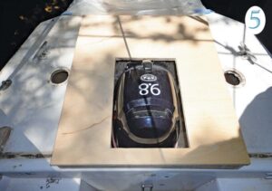
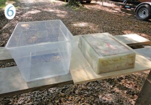
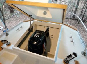
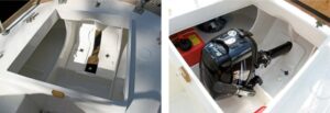
We then set the motor back in to ensure we had adequate clearances and to get accurate measurements for the height of the hatch framing and lid (photo 5). This 9.8-horsepower motor needed 8 inches of clearance above deck level. Instead of making the framing unattractively tall, I made it 3 inches high and raised the center section of the ¾-inch plywood lid 5 inches by glassing to it a piece I made by laminating fiberglass and a ¼-inch plywood core inside a suitably sized plastic storage bin (photo 6). The motor’s throttle handle protruded above the motor head in the tilted-up position, so to keep the hatch as low-profile as possible, I cut 1 inch off the end of the handle. (The rubber cover can be glued back on to the shortened handle.)
To make the hatch-support flange, or sill, I used four pieces of ¾- x 3-inch plywood stood on edge. First, I epoxied the two side sills to the deck and drove in screws from underneath. Then I set the end pieces in place, traced the line of the deck camber on their bottom edges, cut them to fit, radiused the edges, and glassed all the pieces inside and out. The aft sill received an additional 1½-inch-high frame on the outside. That double thickness helped stiffen the deck and gave a flush surface for installing the hinges between the teak frame of the hatch lid and the sill. To add even more support for the area cut out for the enlarged hatch, I added a layer of ½-inch plywood under the aft center of the deck. I made sure to leave enough clearance under the taffrail flange so I could reach the fasteners for the new external chainplate, mooring chocks, or other deck hardware.
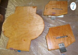
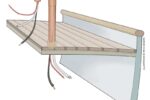
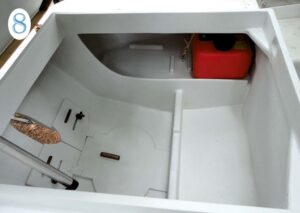
With the motor in the tilted-up position, I used a cardboard pattern to make two ½-inch plywood sliding boards to fit around the motor shaft and cover the transom slot (photo 7). They each have a horizontal slot and a pair of 2½-inch 5⁄16 flat-head stainless steel machine screws countersunk from the outside of the transom and epoxied in place. Two knobs on the inside tighten to lock the boards in the open or closed position. The nearly circular hole in the hull was too wide to seal with sliding doors, so I covered it with a plywood hull plug held by a wooden cleat forward and secured aft by two metal tangs on the sliding boards (photo 8). The idea is not to make the hole watertight—that would be impractical—but to reduce the amount of surging water that enters the well when sailing in large seas and to allow the water that does enter to drain back out.
We removed the motor once more to construct a third buoyancy chamber between the motor-mount board and the cockpit bulkhead. We angled the ½-inch plywood panel downward to drain aft and just low enough to allow the motor-tension handles to be turned. Once it was glassed in place, I drilled 1-inch holes in the corners to allow any water that splashes over the motor-mount board to drain into the motor well and back into the sea. That plywood also added significant strength to the highly stressed board.
Finishing details
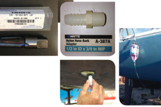
The many details to finish the project included adding eye straps and wooden cleats to secure the gas tanks, a tether to prevent the hull-hole plug below the sliding boards from being lost overboard during insertion or removal, a latch for the front of the lid, a rubber gasket under it, and a lid-support spring. Also, I bolted the motor to the mount to prevent it from vibrating out of position. Since these holes are in a wet area near the water, I drilled them to ½ inch, injected thickened epoxy with a syringe, and then redrilled them for ¼-inch bolts.
For access from the cockpit side lockers to the sealed lockers under the gas-tank shelves, I installed 6-inch screw-out deck plates in the lower vertical bulkhead. Because there is no inboard engine and drivetrain in need of access, an obvious future project would be to make the cockpit lockers watertight. Aside from protecting these areas from accidental flooding, sealing them off from the bilge would allow fuel, including spare cans of gas, to be stored more safely.
I ran the wiring from the motor’s electric starter and alternator, as well as for the stern light and two pole-mount solar panels, through a hole high in the cockpit bulkhead and sealed it with caulk. If I were concerned about chafing, I could have run the wires through a cable clam. A bilge pump outlet hose can be similarly run through the bulkhead with caulk to prevent leaks into the cockpit side lockers.
Having removed the original backstay chainplate knee, we fabricated a beefier replacement external chainplate from ¼ x 1½ x 12-inch stainless steel flat bar bent to fit over the taffrail. Similarly, with the mainsheet traveler gone, we added a three-point end-of-boom sheeting tackle.
I sanded and partially faired the inside surfaces of the outboard well and gave them two coats of InterProtect epoxy barrier coat instead of primer and paint. Because Barbara J was getting repainted inside and out, we sanded, faired, and primed the afterdeck and outside modification areas, and painted them with Interlux Perfection two-part polyurethane.
On the horizontal surfaces, we added non-skid grit as used on the rest of the deck. (More recently, I’ve switched to KiwiGrip, which I find improves traction and is faster to apply.) Although optional, it made sense to fill in the prop aperture in the hull and rudder. This increases the boat’s performance by reducing drag and makes the rudder more effective. The aperture can be filled using foam board or laminated plywood fiberglassed and faired.
Performance
The owner of Barbara J has sea-trialed the outboard well on several short passages offshore along the coast of Georgia, as well as on a round trip to the Bahamas. The performance was even better than expected, with the motor easily handling moderate waves and headwinds in ocean inlets. During a day of strong wind against tide, the prop did briefly come out of the water a few times, but not enough to cause him to turn back. Another great feature is that, by swiveling the motor for side thrust, these long-keeled boats can be made to turn in their own length—something that could never be done with an inboard engine.
How much horsepower?
In 2016, on another Alberg 30, I made a passage from Connecticut to Brunswick, Georgia, with a 6-horsepower motor in a similar outboard well. We used the motor in a variety of conditions, including motorsailing 200 miles of the ICW from Norfolk, Virginia, to Beaufort, North Carolina. A useful technique when encountering headwinds on any relatively underpowered sailboat is to reef the main, sheet it in tight, and motorsail in zigzags 20 degrees either side of the wind. With the mainsail adding drive and a steadying effect, the motor can supply enough thrust to push the boat forward at a surprisingly effective rate. On that trip, we found that we averaged 10 miles per gallon at nearly full throttle. We carried extra gas cans that extended our range to 150 miles, which is more than most of us will need. Because there was plenty of space, the owner of Barbara J has added two more 3.1-gallon gas tanks to make a total of over 12 gallons. When one tank is empty, he can snap the fuel line onto another tank and carry on.
The question always arises if 6 or even 9.8 horsepower is enough for a 30-foot boat. That depends on your expectations and what type of sailor you are. As with everything on a boat, you need to be aware of its limitations. Top speed in calm conditions for the 6-horsepower motor is 5.5 knots, but that drops off quickly in strong headwinds and waves. The 9.8 pushes Barbara J at up to 6.5 knots and has nearly as much effective power as a typical inboard engine without the hassles of wasted space, oily bilges, and the need either to become a proficient diesel mechanic or to bring one to the boat from time to time.
I still get a thrill each time I hoist sails on my Pearson Triton and tilt the motor up for drag-free sailing. I can relax as I sail right over those fish traps without fear of fouling a propeller. But adopters of this conversion must be prepared for protests from fellow sailing-club members when they start to win more races.
Tools, Materials, and Costs
Tools
- Drill with bits and countersink bit
- 4 1⁄2-inch angle grinder with metal-cutting discs to cut fiberglass, and a backing pad and 36-grit discs for shaping
- Jigsaw
- Reciprocating saw (Sawzall)
- Circular saw or table saw with 60-tooth carbide-tipped blade
- 5-inch orbital sander with 80, 120-grit paper
- Router with 1⁄4- and 3⁄8-inch round-over bits
- 3⁄8-inch Forstner bit for bungs in teak hatch-lid trim
- 1-inch and 2 1⁄2-inch hole saws
- Standard tool kit (hammer, wrenches, screwdrivers, etc.)
Materials
- New or used Nissan or Tohatsu 9.8-horsepower outboard motor model MFS9.8BEFUL and two 3.1-gallon gas tanks (onlineoutboards.com)
- West System epoxy resin and hardener: three 1-gallon kits
- West System 406, 407 fillers
- Medium-weight fiberglass cloth: approx. 4 yards x 48 inches
- 2-, 4-, and 6-inch fiberglass tape: 50 feet each (minimum)
- 4 x 8 sheet of 1⁄2-inch marine plywood: one
- 4- x 4-foot half sheet of 3⁄4-inch plywood: one
- 3⁄4 x 1 x 8-foot pine or hardwood lumber: three
- InterProtect 2000E white barrier coat: two quarts
- 2-part primer and paint as needed for repainting afterdeck
- KiwiGrip or other non-skid paint: one quart
- 3⁄4 x 1 1⁄2 x 8-foot teak hatch trim: one
- #10 flat-head stainless steel sheet-metal screws: assorted lengths between 1 and 2 inches
- 1⁄4 x 1 1⁄2 x 12-inch stainless steel plate for new external backstay chainplate
- Moonlite Marine 0115 Big Hatch Holder spring (defender.com)
- 5⁄16 x 2 1⁄2-inch flathead machine screws: two, plus four stainless steel washers
- 5⁄16-inch plastic knobs with threaded hole: two (mcmaster.com #5993K84)
- Chromed brass latch
- Four stainless steel eye straps and webbing with snaps or 1⁄4-inch line to secure gas cans
- 1⁄4- x 3⁄4-inch x 6-foot rubber gasket
- 3M Black Super Weatherstrip Adhesive
- West Marine Multi-Caulk sealant or similar
- Dust masks, gloves, goggles, acetone, alcohol, rags, paper towels
- 2- and 3-inch chip brushes and fiberglass roller
Mainsheet tackle from Garhauer (garhauermarine.com):
- MS-SJ swivel jam with deck mount
- 30-14 US single block with becket
- 30-19 US single block with swivel stand-up deck plate
- 30-17 US double block with adjustable shackle for end of boom
Costs
Someone with adequate skills (practiced on less complex boat repairs) and with the assistance of another as needed should be able to complete this or a similar project in 90 to 100 hours. In this instance, the motor was purchased used for $1,100 and the other materials cost about another $1,100. Even using a new motor, the cost, excluding labor, is significantly less than that of a new diesel engine. For someone who appreciates the simple functionality of the outboard-motor solution, the relatively low cost is a bonus.
James Baldwin completed two circumnavigations in his Pearson Triton, Atom, and has written three books on his adventures as well as several articles for Good Old Boat. Based in Brunswick, Georgia, James and his wife, Mei, work to assist other cruisers to prepare themselves and their boats for offshore voyages. Find more, including a video of this project, at www.atomvoyages.com.
Thank you to Sailrite Enterprises, Inc., for providing free access to back issues of Good Old Boat through intellectual property rights. Sailrite.com