Making it himself, he controlled both the design and the budget
Issue 123: Nov/Dec 2018
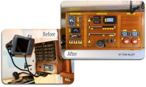
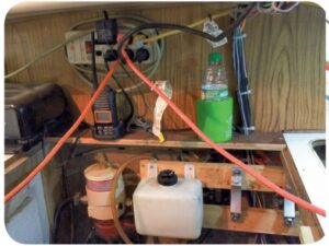
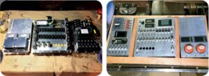
While the electrical system aboard our Alberg 35, Tomfoolery, might have been state-of-the-art when she was built in 1965, it was never intended to meet the needs of a present-day cruising sailboat. The original 12-switch DC distribution panel was no longer adequate, and the original AC system consisted of two wires (no ground!) that went straight from the shorepower connector via a 30-amp fuse to a single outlet in the galley and the original water heater. I had made minor updates over two decades of owning her, but it was becoming clear that a major upgrade was in order, even if only for the sake of tidying up some of the “temporary” additions made over the years. When the need for a new panel became obvious, I started by figuring out first what I wanted, and then what I needed. This was harder than it sounds.
Plenty of good references describe how to develop an electrical “budget” for a boat. This pretty much involves writing down what devices are used and for how long during a typical day aboard and totaling up the number of amp-hours consumed. Next, and this can get a little tricky, is deciding how these various loads should be grouped. Should they be controlled from a large centralized electrical panel or from multiple smaller panels located in various areas of the boat? And how many switches will be needed for the most convenient use: a switch for each area, for each function, or for each device? Another important consideration is the electrical functions that are not used on a daily basis but frequently enough to be designed into the distribution system. Finally, should the panel and system suit present needs only, or should they have capacity designed in for future expansion?
After creating a number of lists of features I thought would be needed or desired in a new electrical panel, I pulled out catalogs from the major chandleries and started looking at commercial electrical panels. Two things were apparent. What I wanted was simply not available as a premanufactured unit, and getting anything close would cost more than 10 percent of the value of my boat. Obviously, this wasn’t going to work, so I started looking at options for fabricating my own distribution panel.
A search among various vendors and online sources assured me that I would be able to source all the parts needed, so I moved on to the next phase, which was to find a location for the electrical panel. Once I’d decided on that, I could nail down the physical dimensions and begin a detailed design.
Location, location, location
The original electrical panel measured approximately 9 × 12 inches and was located on the bulkhead space between the companionway and the starboard side of the deckhouse. This was nowhere near large enough to accommodate the number of switches I wanted, nor would the cable path accommodate all the wires that would have to connect to the panel.
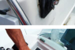
Eventually, I settled on using the space below the companionway under the bridge deck. I had increased the depth to the countertop by 4 inches a couple of years earlier when I replaced the Atomic 4 engine with a Westerbeke diesel. Using this additional depth sounded to me like a near-perfect solution, plus the open engine space would allow for clear and relatively accessible cable runs.
Preliminary design
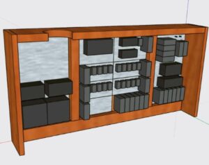
The location defined the new panel’s dimensions, and to begin designing it I used a free software package called SketchUp. This allowed me to experiment with layouts by “sketching” the various components and subassemblies and placing them in different arrangements to test for potential interference or issues that might impact the panel’s functionality or how I might go about installing it.
I decided to divide the panel into three subpanels: an AC distribution panel, a DC main panel for the battery switches and battery monitors, and a DC distribution panel that also serves some other functions (see “Panel Design and Division,” below).
Making the DC distribution panel modular allowed me to standardize a number of components, which I hope will simplify use and upkeep of the electrical system in the future by reducing the diversity of spare parts needed. All the breakers (except for two dedicated to specific purposes) are 20 amps, and all the DC wiring is AWG 10, as are the associated connectors. While this is oversized for most loads, it will reduce voltage drops to sensitive equipment.
I used only two types of connectors: spade lugs for “permanent” connections and Anderson Powerpole connectors where I wanted quick-disconnect capability. All the connectors are the crimp type for durability in a marine environment.
Construction
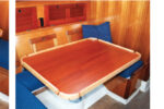
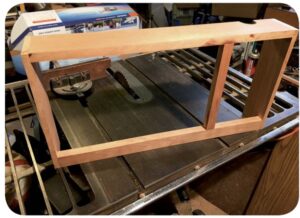
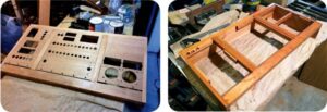
When I’d worked out most of the design details, I commenced construction of the panel, starting with the frame. I had some cherry left over from a prior project, and it was quick work with a table saw and planer to cut the frame and assemble it.
Next would be the panels. Being a woodworker, I like the look of natural wood, but making the panels out of thin plywood gave me concern. To support the banks of switches, meters, and circuit breakers, I would need ¼-inch plywood at the least. Most of those components are not designed to be mounted to anything that thick, so I decided to make the panels out of aluminum, which, as well as being soft enough to be worked with woodworking tools, offers some safety by providing electrical shielding. When the metal panels are grounded, any loose wire in the panel that touches the faceplate will instantly ground out instead of finding a path through someone touching one of the switches or the faceplate. While this isn’t a terrible concern with the 12-volt house power, it is with the 120-volt shorepower.
Fabricating the panels was straightforward but time-consuming. I started with a 2 × 4-foot sheet of 3/32-inch-thick aluminum from a local metal-fabrication shop and used a table saw to cut the faceplates for each section of the larger distribution panel.
Before beginning the detailed cut work, I laid out all the components on each panel for a quick visual “sanity check” to finalize the layout.
To measure and mark (scribe) the location of each hole that had to be made, I used a machinist’s square and an awl. Because aluminum is relatively soft, the awl can be used almost like a pencil to scratch lines into the surface. Where lines intersected, the surface scribes provided a good reference for a center punch, which in turn would help prevent a drill bit from wandering as I drilled the holes. This process ensured a high degree of alignment so that everything would “look straight” when the panel was completed.

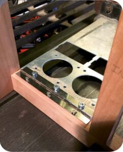
Using a drill press allowed me to drill holes precisely where I’d marked them and ensured that the drilled holes would be perpendicular to the surface. A drill bit was the obvious tool for making smaller holes, but I used a hole saw for the larger round holes, such as those for the battery-disconnect switches.
Rectangular holes were a bit more challenging. For these I used a Dremel tool with an abrasive cutoff wheel to cut the straight sides and a hacksaw blade to make clean corners. While an oscillating multitool might have made quicker work of the task, the Dremel tool provided greater precision and control.
I made the three faceplates one at a time and not in parallel, starting with the simplest panel (the DC mains) and progressing to the most complex (the DC distribution section). Using the experience gained with the AC and DC main panels allowed me to refine my fabrication techniques. This improved the accuracy with which I could drill the holes, but did not, unfortunately, improve the attention span of the fabricator. I still managed to drill a hole in the wrong place and had to start over and remake the DC distribution panel. The lesson here was that you can redrill a small hole to make it bigger, but you can’t redrill a big hole to make it smaller.
When I was satisfied with the faceplates, I attached their bottom edges to the frame with piano hinge, then mounted the components for another test fit and some additional visualization of what the final product would look like.
Cosmetic considerations
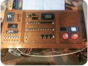
At this point I had to decide whether I would simply paint the aluminum panels or if I would try for a less industrial look. Given my preference for wood, I decided to do the latter by covering the panels with mahogany veneer. The process was relatively simple. I cut sheets of veneer to the approximate size of each panel and then prepped both the aluminum plates and veneer pieces with two coats of contact cement. Once the cement was dry to the touch, I pressed the plates and veneer together and rolled them with a veneer press to ensure a good flat bond.
I used a razor to cut out the openings for displays, switches, and breakers, leaving the holes intended for future expansion covered, as it would be a simple matter to open them up with a razor when the time came. After installing the panels on the frame for a final test fit, I added cleats to the inside of the frame to function like a door jamb so the panels would sit flush with the surface of the frame. The cleats would also receive screws in the top corners to hold the panels closed.
The woodworking was now complete, and I applied several coats of varnish to all the wood surfaces. Because the panel would be indoors (and I was on a budget), I used a varnish from the home center, rather than a marine-grade brand. I allowed each coat to dry, and sanded the surfaces with 200-grit paper between coats.
Final assembly
The moment of truth was near. I bolted the components to the panels and then attached the panels to the frame. Being a little anxious, I added some temporary wires to the panel so that I could plug it into an AC outlet in my shop, connect the charger/inverter, and tie in a 12-volt battery. Everything lit up beautifully, and I was able to test some of the panel’s basic features. I verified that the meters were functioning, tested the inverter, and configured the displays. I also configured the charger for the AGM battery banks on the boat.
Finally, it came time to install the panel on my boat and start transferring existing loads from the old panel to the new. This was perhaps the most tedious part of the project. One of the problems was that the boat’s electrical system, having evolved over time, utilized several distribution points. The new panel consolidates distribution in one place, so I had to rewire a good portion of the system.
As I hooked up the switches, I printed labels for them with a label maker. While the labels might not match the classic look of the panel, I expect that I can change them for something more stylish once I’m sure everything works the way I would like it to. The labels are simply stuck on with adhesive, so they will be easy to remove.
AC with an inverter/charger
As part of this project, I replaced Tomfoolery’s battery charger with a combined charger and inverter. We had previously used some smaller inverters to power dedicated loads, but even though one of them was rated for 450 watts, it could not handle the start-up surge of an electric drill motor. Simply upsizing the inverter would have been the easy answer, but the tradeoff is that larger inverters are less efficient at low loads (when there’s just a laptop plugged in, e.g.) because they draw a larger idle current from the battery when not loaded. In the end, I decided to install a 1-kilowatt inverter as a compromise.
In North America, a 30-amp shorepower service is roughly equivalent to 3,500 watts (3.5 kilowatts), which means that not all the shorepower service can be passed through the 1-kilowatt inverter. Therefore, the shorepower system needs to be split into two systems: one that is backed up by the inverter, and one that goes directly to the shorepower source. Besides, it makes no sense to try to run any sort of electric heater (be it to heat water, heat the cabin, or cook food) using the ship’s batteries. These loads are best kept separate.
For safety reasons, it’s essential to keep the AC system that is powered by the inverter completely separate from the AC system that bypasses the inverter and supplies other devices on the boat (see “Inverter Essentials,” July 2015. –Eds.). This means that the neutral and ground wires from inverter loads must go back to the inverter only and not be tied to the neutral and ground used by the rest of the shorepower system. Circuitry in the inverter will tie the neutral and ground back to shore when shorepower is available, and will open that connection should shorepower fail and the inverter take over. This will isolate the boat from shore and ensure the AC system has a proper (and safe) ground when under battery power.
Expectations met
After a summer of use, the new panel has proven to be a worthwhile upgrade. It has enabled me to add the multiple components needed to properly monitor and maintain a 21st-century marine electrical system that includes battery monitors, a built-in battery charger, an inverter, and many of the electronic tools and toys we take with us when we go sailing. Designed to be flexible, it also allows for future growth and can, if needed, be reconfigured.
Best of all, I met my goal of creating a functional distribution panel on a budget. Not counting the cost of the inverter/charger, the panel and its components cost less than $500 to assemble, and it provided a solution custom-fit to the needs presented by my boat.
Panel Design and Division
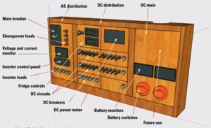
At the top of the AC distribution panel is the main circuit breaker for shorepower (along with a built-in polarity indicator) and red breakers for “raw” shorepower. Below them is a meter to monitor AC voltage and current and a control panel for the boat’s new battery charger/inverter. The white breakers along the bottom are for AC loads connected to the output of the inverter.
Circuit breakers are expensive, so when designing the DC distribution panel, to keep costs under control, I decided to assign DC breakers to groups of circuits rather than to individual loads. For example, cabin lighting could be organized into two groups (port and starboard), but power to a particular cabin (saloon, head, or V-berth) could be controlled by a switch. Individual fixtures typically have their own switches.
High-draw loads, like the SSB transceiver or electric windlass, do warrant dedicated breakers, and these are located along the bottom of the panel. Prior to installing the panel in the boat, I fitted some cigarette-lighter sockets for the ubiquitous cell-phone chargers. They are to the right of the “high-draw” breaker bank.
I located “miscellaneous” functions at the top of the center panel. This included a section devoted to our refrigeration system that included a breaker for the compressor, a switch for a small circulating fan, and a couple of temperature displays.
Also located here is a DC power meter to monitor overall DC electrical parameters such as voltage, current, and energy draw (amp-hours). This meter, which I installed during an earlier expansion to the DC system on the boat, is somewhat redundant to the battery monitors, but it sums the data on the two battery monitors and serves as a fallback should one of the other meters fail.
The DC main panel houses the battery switches for the two house banks. Above each switch is a battery monitor that tracks voltage, current, and amp-hours for that battery bank. The space above is available for anything that might prove useful, such as LEDs to indicate which navigation lights are powered on.
Tom Alley and his family, sailing their 1965 Alberg 35 sloop, Tomfoolery, are active racers and cruisers with the Finger Lakes Yacht Club in Watkins Glen, New York. Tom has been a member of the US Power Squadrons since the late 1980s, when he got serious about sailing and having fun on the water. He has been a Squadron Education Officer for longer than he cares to remember. He also manages the Alberg 35 User Group website (www.Alberg35.org). When he’s not sailing, tinkering with his boat, scuba diving, or hanging out with fellow amateur radio operators, he works as an engineer to support his sailing addiction and, if there’s any money left over, send his kids to college.
Thank you to Sailrite Enterprises, Inc., for providing free access to back issues of Good Old Boat through intellectual property rights. Sailrite.com