Sourcing rigging tension creep reveals an old flaw.
Issue 134: Sept/Oct 2020
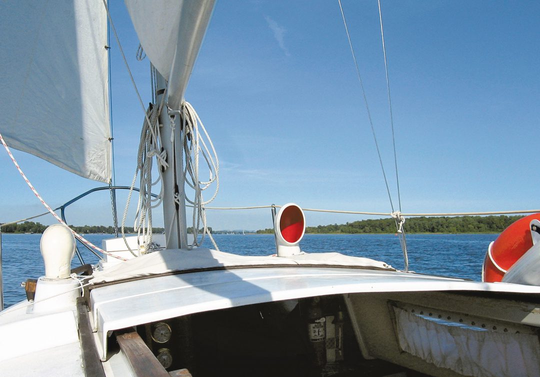
For a few years, the shrouds and stays on Mikula, my 24-foot Seafarer, would slowly lose their tension over the course of each sailing season.
Because I pull my mast each season, I have a habit of marking the turnbuckle screws so I can quickly get them to near-correct tension before using my tension gauge to fine-tune the whole rig. These marks made it plain to see that the turnbuckles weren’t turning, yet my rig was loosening and usually required some tightening at least once during each season.
I did not believe that stretch could be the cause. Mikula displaces only 4,000 pounds and flies only 260 square feet of sail—3/16-inch rigging is plenty for the loads generated under sail.
I was a bit concerned and determined to find out what was going on. At the end of one sailing season I towed Mikula home, figuring that having my workshop and tools nearby would make finding the problem and correcting it easier.
The Seafarer 24 is a solidly built boat; the mast is deck-stepped, and the mast load is transferred to the swing keel housing via a 3-inch-diameter aluminum pipe compression post with ¼-inch walls. I could not detect any visible deformation on the hull, deck, or cabin, and all the chainplates looked perfect, with no leaks around them or loose bolts.
Sitting on the V-berth, I contemplated the rig. I’d ruled out stretch. None of the chainplates were pulling out. The mast could not be compressed. I ruled out hull deformation, deciding that the boat was too strongly built to be so easily deformed. That left one cause I’d not explored: The mast was somehow sinking into the hull. But how could that be possible?
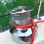
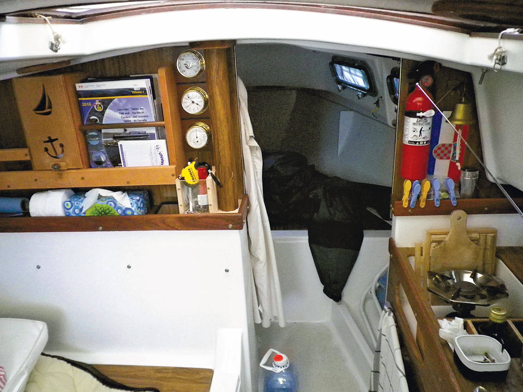
I turned my attention to the compression post. Like many boats, the Seafarer is built with a fiberglass liner; in my boat, the lower half of the bulkhead between the saloon and forward cabin is incorporated into that liner. It resembles a rectangular box standing on its side, and the compression post sits inside this box at the end of the port-side bulkhead, which extends farther into the cabin than the starboard bulkhead.
While the top section of the compression post was totally visible, the lower section vanished into the box-like bulkhead, invisible and inaccessible.
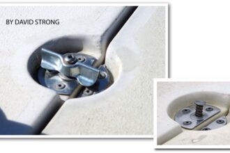
The top surface of the bulkhead was covered with a wooden shelf, through which the post passed via a hole cut into the shelf. After removing the shelf’s trim pieces, I slid it upward, which exposed an oblong hole in the top of fiberglass bulkhead. I looked inside.
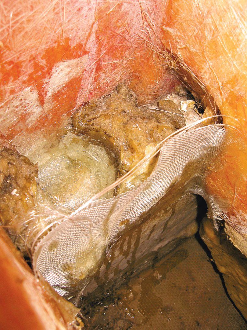
At first, I did not see anything suspicious—the bottom of the post was sitting on a lump of fiberglass which was obviously on the top of the swing keel housing. It did not look nice, but I figured it had to be good; Mikula was at that time over 35 years old, and it was still holding together fairly well. I tried moving the compression post—up, down, around—without success.
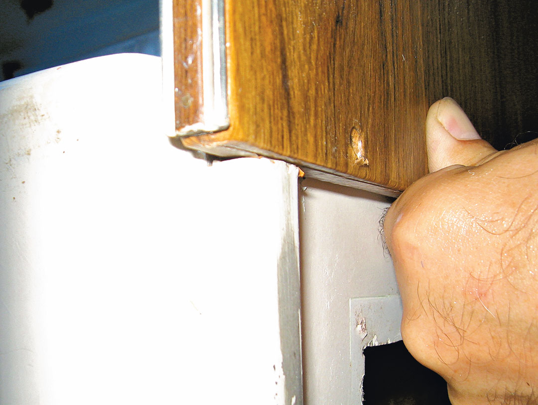
I made myself a coffee and sat there for a while, thinking and looking. And then I realized something was not as it should be. Above its fiberglass base, the remainder of the bulkhead is finished with plywood. I realized that this plywood portion was not really aligned with curvature of the overhead and the cabin side.
On closer examination, I also found that there was a lip molded on the end of the fiberglass bulkhead inside the forward cabin. Instead of sitting on that lip, the lower edge of plywood bulkhead was actually below it and leaning away from the vertical surface of the bulkhead box. I vaguely remembered that I had noticed all of these things before and had attributed them at the time to sloppy finishing work. But now I was wondering: Could this actually be a sign of cabin deformation? Was I finally on to something here?
My conclusion was that the mast compression post somehow was pushing downward. What I did not understand is why everything did not return upward when the mast was removed. Was it possible that cabin was deformed beyond elasticity of fiberglass?
The only way to find out was to push the cabin top up and see what would happen; would the plywood bulkhead then align better with the fiberglass bulkhead and lips on the overhead and cabin sides? Would I be able to move the mast compression post then?
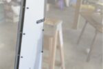
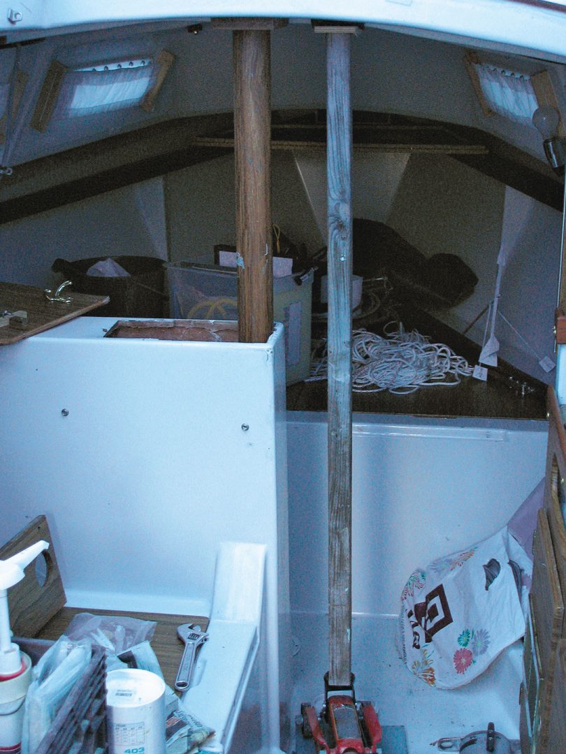
I took a length of 4 x 4-inch wood post, laid a piece of thick plywood on the cabin floor, and positioned a hydraulic car jack to create lifting pressure via the wood post to the cabin overhead, as close to the compression post as possible. I inserted a piece of thick rubber between the wooden post and overhead to protect the gelcoat surface.
As I slowly applied pressure, I closely watched the cabin sole—I did not want to end up with a car jack breaking through the floor and ending up in the bilge! But the plywood piece spread the load on a large enough surface, and I could not detect any floor deflection or hear cracking fiberglass.
After every small stroke of the car jack handle, I tried to move the compression post, and I also went forward to check the plywood bulkhead. I loosened all the screws holding the plywood bulkhead so I could check if by moving the bulkhead slightly it would fit better. Finally, the plywood bulkhead was sitting on the lip of the fiberglass bulkhead, and it aligned perfectly with the overhead and sides of the cabin. There was now about a half-inch gap between the overhead and compression post as well.
I grabbed the compression post, and after some wrestling I was able to lift it completely from the fiberglass bulkhead box. Finally, I could have a really good look inside.
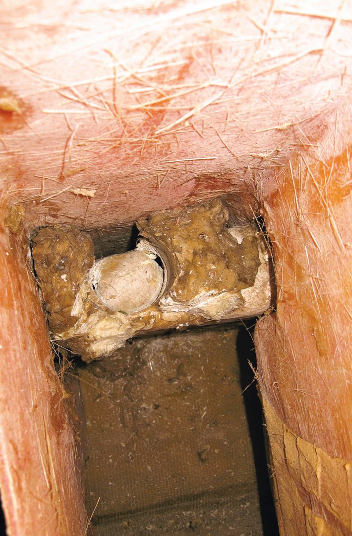
The compression post stood on top of the lump of thickened polyester (or vinylester, or even maybe epoxy), but without any kind of flat, hard base. While the builders had installed a piece of flat metal between the cabin overhead and top of the compression post—which is the proper way of doing it—they did not follow suit on the bottom.
Made of pipe open at both ends, the compression post was slowly grinding its way down and through the lump of whatever thickened goo they had used. Granted, it had taken nearly 30 years to sink nearly half an inch, but it would have been much better had they installed a 4-inch-square piece of aluminum or stainless plate there instead.
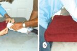
From there on, it was an easy fix—if sometimes awkward. To gain enough access to the inside of the bulkhead, I had to enlarge the oblong hole in its top so that I could go in with both hands and arms. Even with the hole enlarged, it was a tight fit to access the swing keel housing, and since it was about 24 inches down to the area where I had to work, it’s a good thing I have long arms.
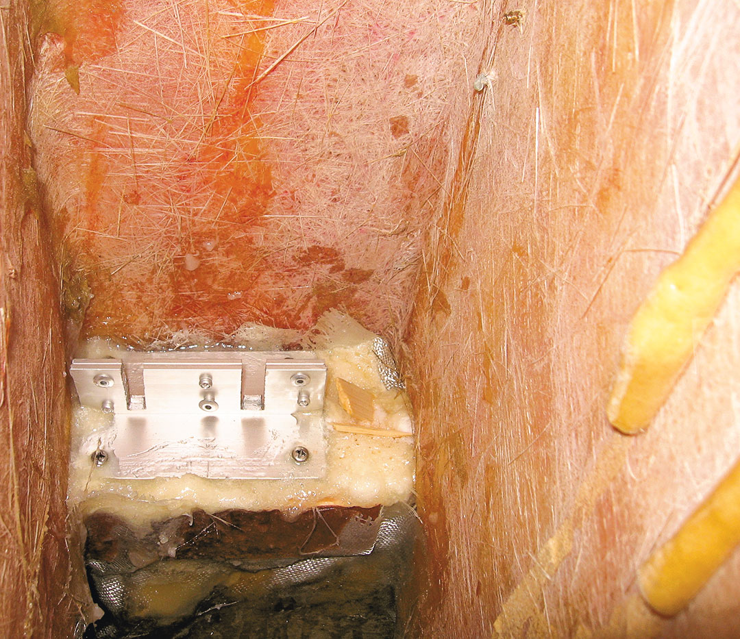
I fabricated a simple base for the compression post from two short sections of aluminum L-profile, leaving two vertical notches to hold the compression post in place and riveting the sections together.
In the area where the new base would sit, I vacuumed everything the best I could, then used a stiff brush attached to a long handle to wash the area with acetone. I epoxied a piece of glass cloth on one side of the goo lump to create a containment area so that I could pour thickened epoxy on top of the keel housing where I would glue in the new base.
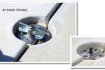
I installed four 2-inch-long #10 machine screws on each corner of the base’s horizontal surface to act as anchors buried in thickened epoxy.
After the epoxy cured, I made a batch of thickened epoxy and filled the cavity completely before positioning the aluminum base, gently rocking it back and forth to ensure there were no voids beneath it. I did my best to make it horizontal both lengthwise and athwartships. That required a few small pieces of wood to wedge the base against the vertical sides of the bulkhead interior until the epoxy cured. I did not bother to remove them afterward, since no one would likely ever see them there.
During all that work, I left the hydraulic jack and wooden post in place to hold the cabin top at the correct height, and the next day I carefully measured the distance from the new base surface to the metal plate on the cabin ceiling. I then shortened the compression post to the proper new length.
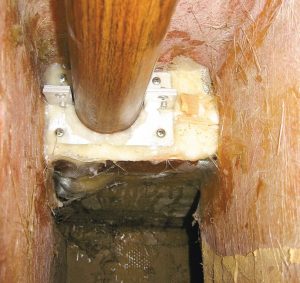
I made a small batch of thickened epoxy and poured it in a circular pattern on the aluminum base where the compression post would sit. Then I maneuvered the compression post inside the lower bulkhead, eventually inserting it onto the new aluminum base. With the post nearly vertical, I jacked up the cabin overhead an extra half inch to bring the post into a completely vertical position. Then I slowly released the pressure in the hydraulic jack.
The cabin top came down, sitting exactly on top of the post. There was a very slight pressure on it, but I could still move the post a bit—perfect! I refastened the plywood bulkhead after that; it looked much better now, aligned as it should be with cabin and bulkhead contours around it.
The rest of the work involved reinstalling the wooden trim and refastening a wooden collar that held the top of the compression post in place.
As expected, my rig stayed tuned all season long.
Zoran Glozinic is a retired business professional who has been messing around boats and old cars all his life. He currently lives in Laval, Quebec, where he divides his free time between a good old English bilge-keel boat and an 18-year-old Saab car.
Thank you to Sailrite Enterprises, Inc., for providing free access to back issues of Good Old Boat through intellectual property rights. Sailrite.com