The Bristol 29.9 seemed too small for a windlass, but doctor’s orders demanded one.
Issue 138: May/June 2021
As we embarked on the refit of Pegu Club, our 1977 Bristol 29.9, my husband, Jeff, and I made the conscious decision to forego a windlass. We were prepping for a cruising life and were determined to keep things simple. Why have a windlass when Jeff was perfectly capable of weighing our 22-pound anchor?
The answer came on Christmas Eve, when Jeff landed in the ICU with a diagnosis of congestive heart failure.
After two weeks, the hospital sent Jeff home with permanent lifting restrictions. We considered a manual windlass, but then envisioned a worst-case scenario in which I was incapacitated, and Jeff needed to weigh anchor quickly. An electric windlass was the best option, but how would we install one on a boat not originally designed for one? We searched online for inspiration and information, but we couldn’t find any examples of a Bristol 29.9 with an electric windlass. We were on our own.
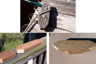
The first obstacle we faced was positioning a windlass. There was no space forward of the anchor locker to mount one, and the anchor locker on the 29.9 is only 7 inches deep, barely enough room in there to stow our rode, so no space there either. There seemed only one solution to the location problem: atop the anchor locker hatch. Our plan was to cut the hatch in half athwartships, permanently affixing the forward half as a deck for the windlass and leaving the after portion available to open and access the locker.
We considered a low-profile vertical windlass (the windlass motor is below deck, only the gypsy is above deck), but the rode leaves the gypsy at deck level, meaning that the distance of our fall is limited to the depth of our anchor locker. In contrast, a horizontal windlass sits entirely above deck and the gypsy is a bit higher than the deck, allowing more distance for the rode to fall. In either case, we don’t have an anchor locker deep enough to permit the recommended fall distance, but it was clear the horizontal configuration would give us an edge. We focused our search on a horizontal windlass.
Because Pegu Club’s rode is a combination of 125 feet of 5/16-inch G4 chain and 175 feet of 9/16-inch eight-plait rope, we needed a rope/chain windlass. We selected a Maxwell HRC-8. Though we’re about an inch shy of the specified fall distance for this model, this hasn’t proven to be an issue.
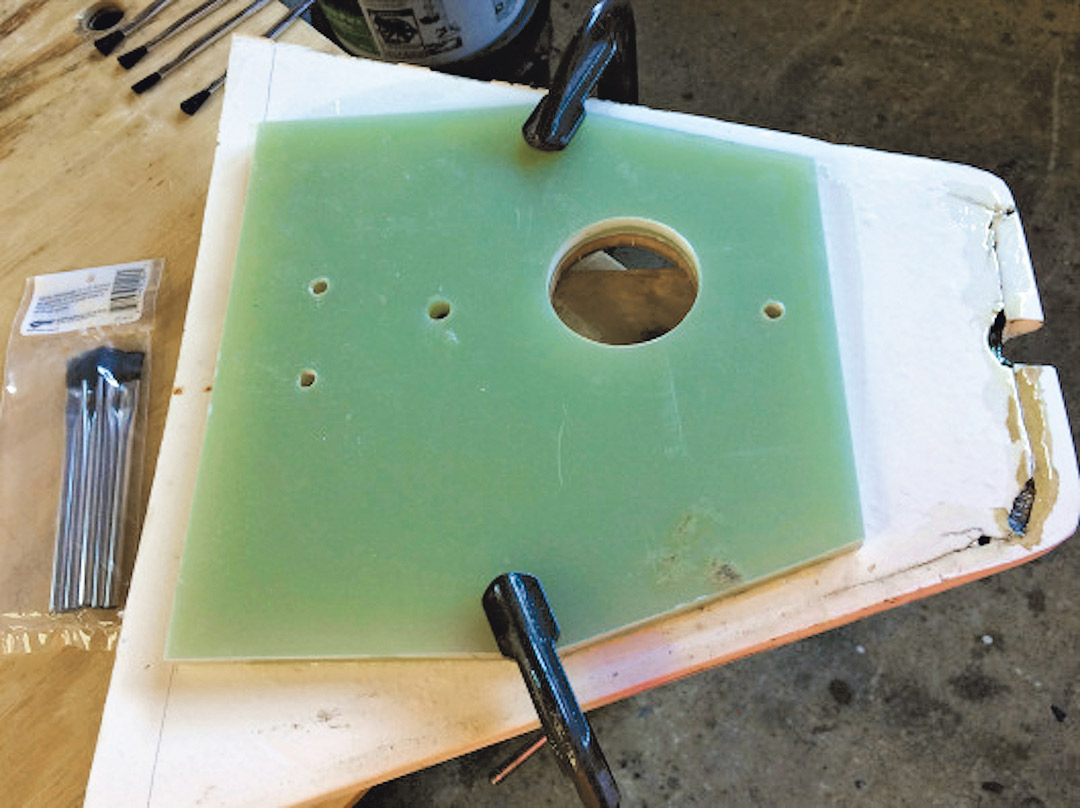
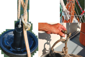
After removing and cutting the anchor locker hatch, we used the manufacturer-provided template to cut holes in the forward part of the hatch, where we would install the windlass. Next, we placed half-inch-thick G10 on the underside of the lid, and using the holes in the lid as a guide, we cut identical holes in the G10. The G10 would serve as a backing plate on the hatch to reinforce it for the windlass install. (We used G10 similarly to reinforce the deck beneath all of our cleats and stanchions, and we were confident in its strength.)
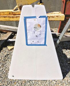
We then did a dry fit of the windlass, the hatch, and the G10 (Whew! We cut the holes in the right places!) before affixing the G10 to the underside of the anchor locker hatch with thickened West System epoxy. Next, we brushed neat epoxy on all of the exposed core.
The next day we installed a cable clam to run the electric cables from the cabin interior into the anchor locker. If water made it into the locker, the cable clam would prevent it from running down below. Fortunately, we were able to use an existing hole from a previously removed anchor washdown fitting installed by a former owner.
One of our concerns was ensuring the windlass wouldn’t rip the locker hatch off the boat, no matter how much load was placed on it. We decided to use a belt-and-suspenders approach by attaching the lid with thickened epoxy and screwing it down around the perimeter, securing the hatch to the solid fiberglass lip of the anchor locker. Between reinforcing the lid and securing it so well, we felt comfortable that if conditions ever resulted in the windlass breaking free, we would have bigger problems to worry about.
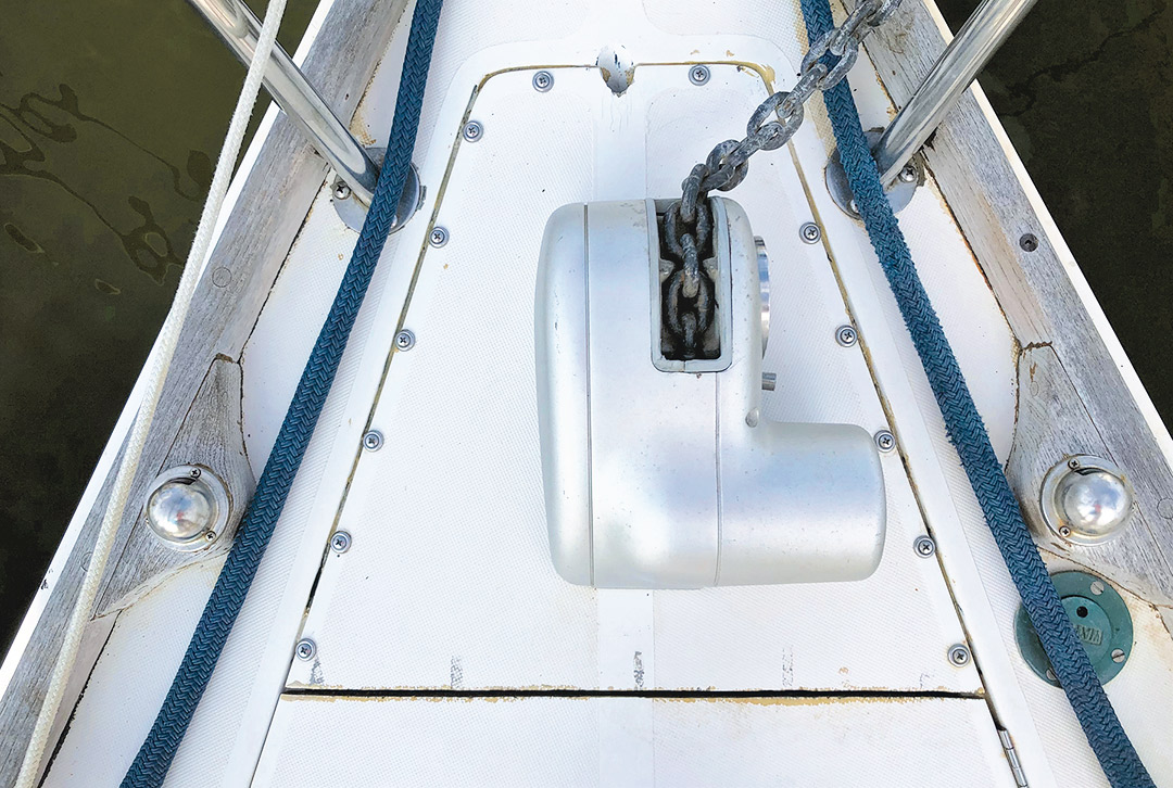
Once we finished the windlass portion of the anchor locker hatch, we cut the piano hinge to size for the remaining hatch portion and installed it. Voila! The windlass was mechanically attached to the boat!
Of course, this was only half of the job completed; we needed to build an electrical circuit for our windlass. With our limited electrical knowledge, the manufacturer’s wiring schematic was daunting. Fortunately, we had electrically savvy boating friends we could turn to when we were stuck.
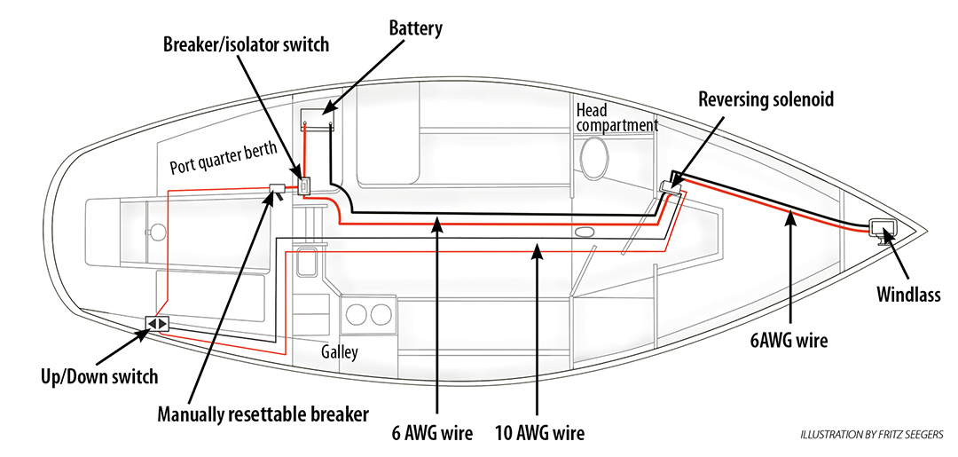
We opted not to install a separate windlass-dedicated battery in the bow. Between the water tank, our anchor, and rode, we felt there was already enough weight forward. That meant we would need to run wires (cables) from the windlass aft to our battery bank under the quarter berth. We also needed to find homes for the up/down control switch, the reversing solenoid, a breaker/isolator switch, and a 3-amp manually resettable breaker.
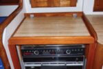
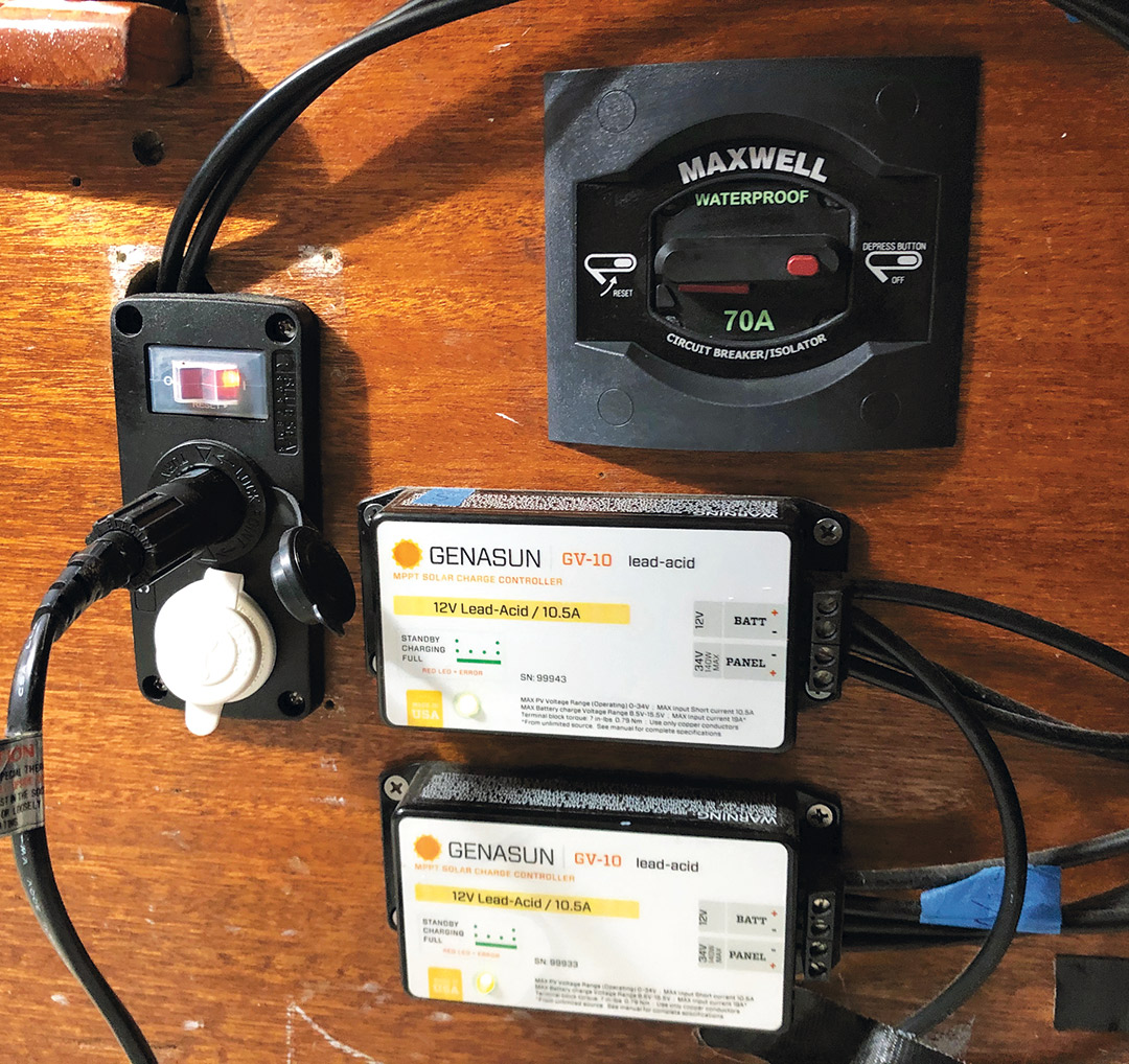
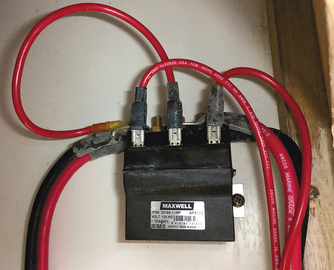
The up/down switch was easy. We wanted to install it in the cockpit so the helmsman could operate the windlass. The reversing solenoid pack went under the sink in the head without trouble. The breaker/isolator switch needed to be located within 6 feet of the batteries, so we installed it on the quarter berth bulkhead. Jeff carefully used a jab saw to cut the hole, while on the other side of the bulkhead I held cables out of the way. (You know you trust your partner’s toolhandling skills when you place your arm uncomfortably close to live cables and a jab saw in action.)
Everything was going smoothly until we came to the 3-amp manually resettable breaker. We spun our wheels for a while trying to decide if we even needed it. We weren’t installing foot switches, and it hadn’t been included with the windlass.
We surveyed our electrically savvy boating friends and received conflicting answers. Ultimately, we concluded that we needed one because it protects the up/down control switch and would also serve as protection for foot switches if we decided to install them in the future.
The breaker was easy to find at the chandlery, but it needed to be installed within 40 inches of the battery, and we were running out of places to cut holes in the quarter berth bulkhead while keeping the breaker within reach. We settled on attaching it to the engine side of the bulkhead with a piece of Velcro. Not ideal, but it worked.
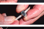
The final step was running the wiring. Without fish tape, it would have been a non-starter trying to pull the size 6 AWG wires from the windlass through impossible-to-reach spaces beneath berths and around tanks to where they attached to the reversing solenoid.
From the reversing solenoid pack, we ran two pairs of wires—10 AWG and 6 AWG—beneath the sole in the head, past the mast, and under the cabin sole. From there, the 6 AWG pair ran to the opposite side of the engine room, where I connected the positive wire to the breaker/isolator switch and then to the battery. The negative 6 AWG wire continued to the battery.
We ran the 10 AWG wire pair through the engine room and up to the cockpit switch. To complete that circuit, we connected another 10 AWG wire to the positive side of the switch and ran it to the 3-amp manually resettable breaker and on to the breaker/isolator. Finally—and not shown in the illustration—the wiring instructions had us attach a small 10 AWG jumper wire from one terminal on the reversing solenoid to another, to complete the negative side of the cockpit switch circuit.
I’ll be honest, there were many times during this project that I thought about the Pardeys and how they got by with a manual windlass and no electrical system, and it sounded pretty good to me. But then, we were finished, and it was time for the moment of truth. After starting the engine, I triggered the control switch from the helm while Jeff stood at the bow. When I saw his thumbs up, my “Whoo-hoo!” echoed throughout our marina. We did it! We installed an electric windlass on a Bristol 29.9.
Like many boat projects, this one didn’t turn out to be particularly difficult, just time-consuming and occasionally patience-testing. Now that we’ve been cruising full-time and anchoring often, I can say that this was one of our top upgrades (not that we had much of a choice given Jeff’s lifting restrictions).
Additionally, having the electric windless enabled us to upgrade to a larger anchor (33 pounds), which lets us sleep more soundly. The electric windlass also makes it an easy decision to re-anchor whenever we think it might be a good idea. It was money and time well spent.
Jeff and Kimberly Boneham have been cruising full-time since September 2018 on their 1977 Bristol 29.9 Pegu Club. Traveling along the U.S. East Coast and the Bahamas, Kimberly posts about the highs and lows of their adventures on her blog, adventuresontheclub.com.
Thank you to Sailrite Enterprises, Inc., for providing free access to back issues of Good Old Boat through intellectual property rights. Sailrite.com