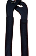
Checking your traveler car shackles for wear can prevent unwanted surprises.
Issue 133: July/Aug 2020
A week after I happened to watch a young sailor on YouTube repair a Harken traveler car, a fellow Sabre sailor experienced an accidental jibe, and his traveler car exploded in the melee. I’m not normally superstitious, but I figured it was a good time to inspect the 26-year-old Harken traveler car on Second Star, my Sabre 362.
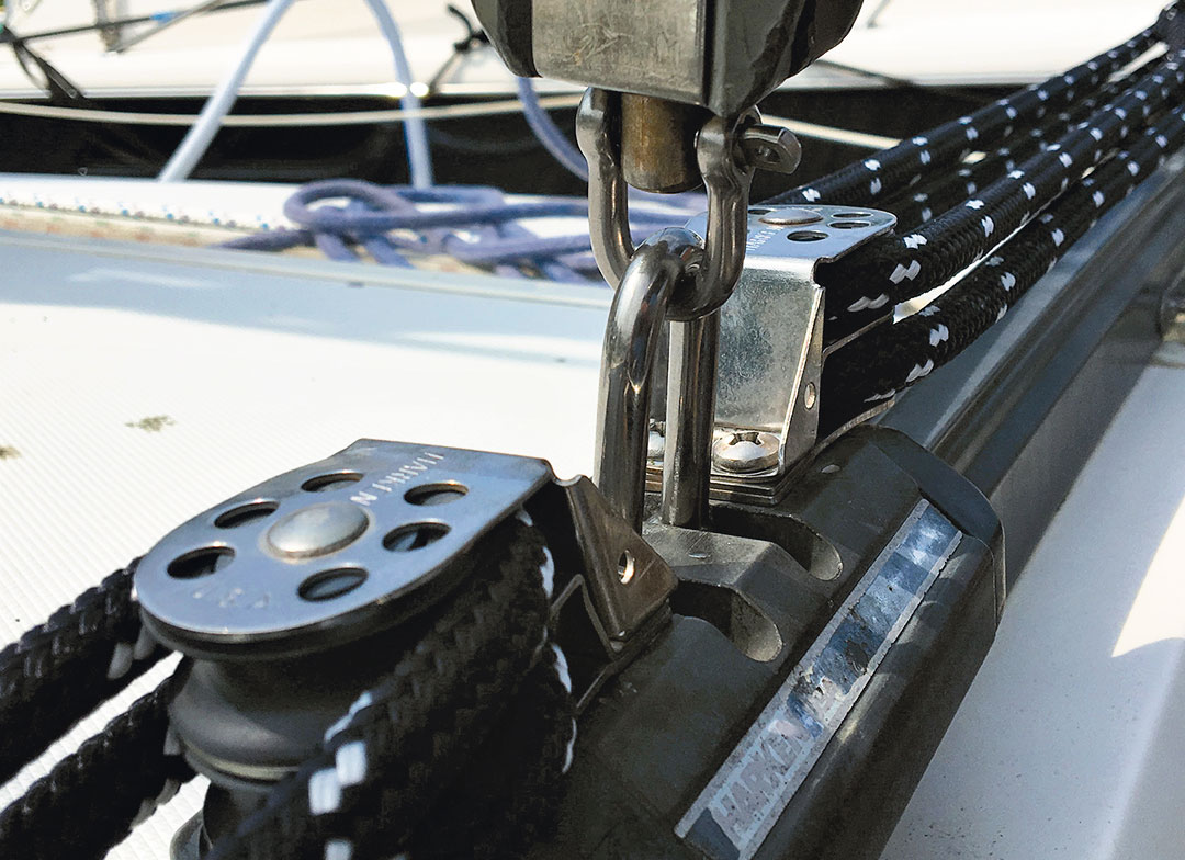
It’s easy to take the traveler car for granted. So long as it rolls smoothly on the track, all seems to be well. However, lurking beneath the lower mainsheet block on most travelers are two shackles that silently grind away at each other, stainless steel on stainless steel. After years of erosion, the shackles may be worn thin and vulnerable to failure.
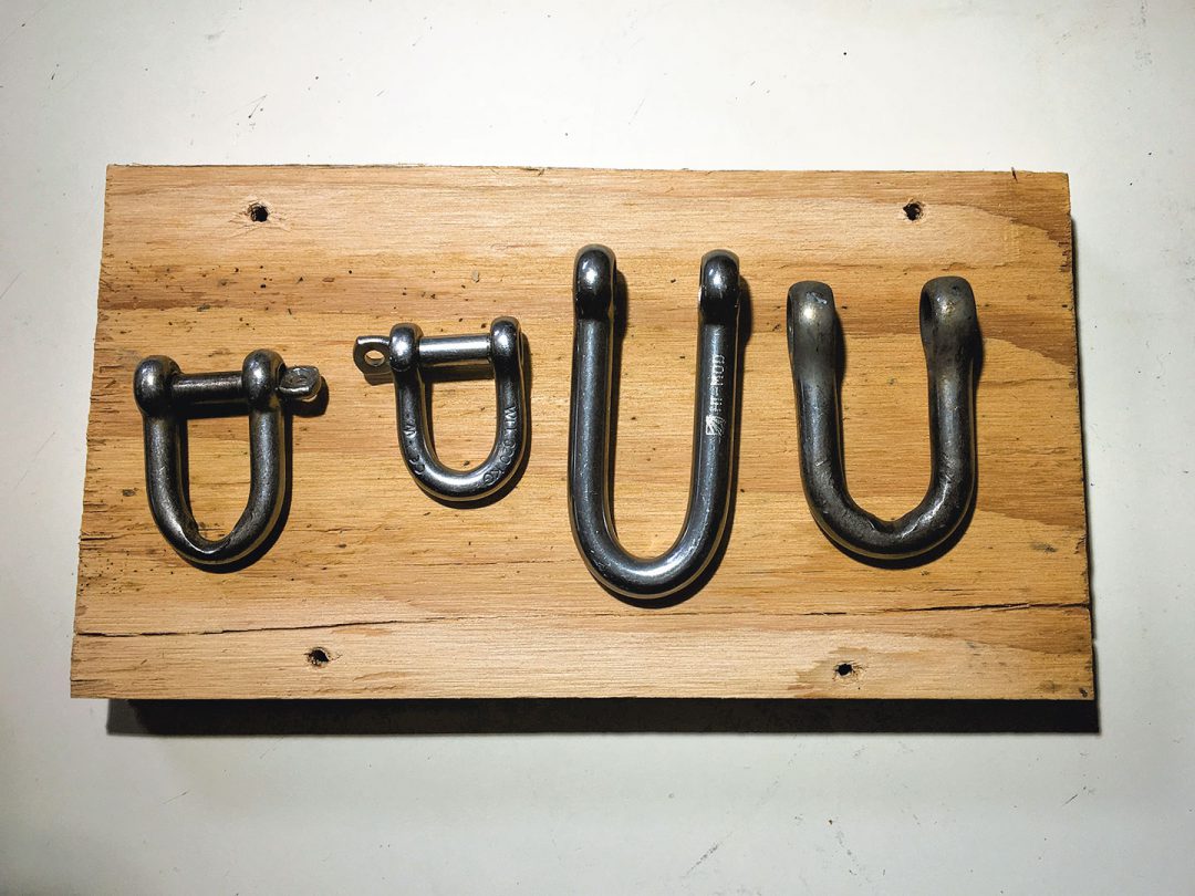
The Harken traveler car is a simple design, consisting of a 5/16-inch shackle attached to the traveler with an interlocking 1/4-inch shackle attached to the lower mainsheet block. Of course, those dimensions are nominal, and when new, the larger shackle measures .315 inches, the smaller shackle .2450 inches.
Inspecting the shackles on my traveler revealed significant wear and an obvious reduction in thickness at the wear points. Where the wear was concentrated, the larger shackle measured .279 inches, an 11 percent decrease in size and strength. The smaller shackle fared even worse, measuring .180 inches, a decrease of 28 percent in size and strength.
Upon closer inspection, I noticed another weak point. The pin holes in the larger shackle were elongated and the sides were thinning. This is particularly troublesome as the holes are not visible without disassembling the traveler car.
How serious is this wear? Quite serious. Let’s do the math.
The small shackle has a working load limit (WLL) of 320 kg or about 700 pounds. A diameter reduction of 25 percent reduces the WLL by 175 pounds, to 525 pounds. Let’s assume the design working load for the traveler is 350 pounds. That is half the WLL and thus provides a 100 percent safety margin. But the WLL of the worn shackle is now reduced by 175 pounds, half of the 350-pound margin that existed. This is an accident waiting to happen.
The cause of the wear is obvious: movement of the shackles while sailing and at the dock or mooring. When the boom swings back and forth, the shackles bear on each other and grind away. Salt, dirt, and grit all compound the problem by adding an abrasive element.
Completely eliminating wear is impossible but stabilizing the boom when the boat is not sailing can help; a simple setup to secure the boom will reduce motion and consequent wear. Doing the same when motoring or sailing in sloppy conditions will also decrease wear. Adding a sacrificial cover to the shackles might also help (and reduce noise), but given that this is a problem 20 years in the making and that replacing the shackles is simple and inexpensive, I’m not inclined to fuss with covers.
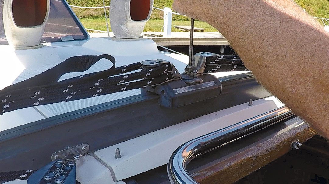
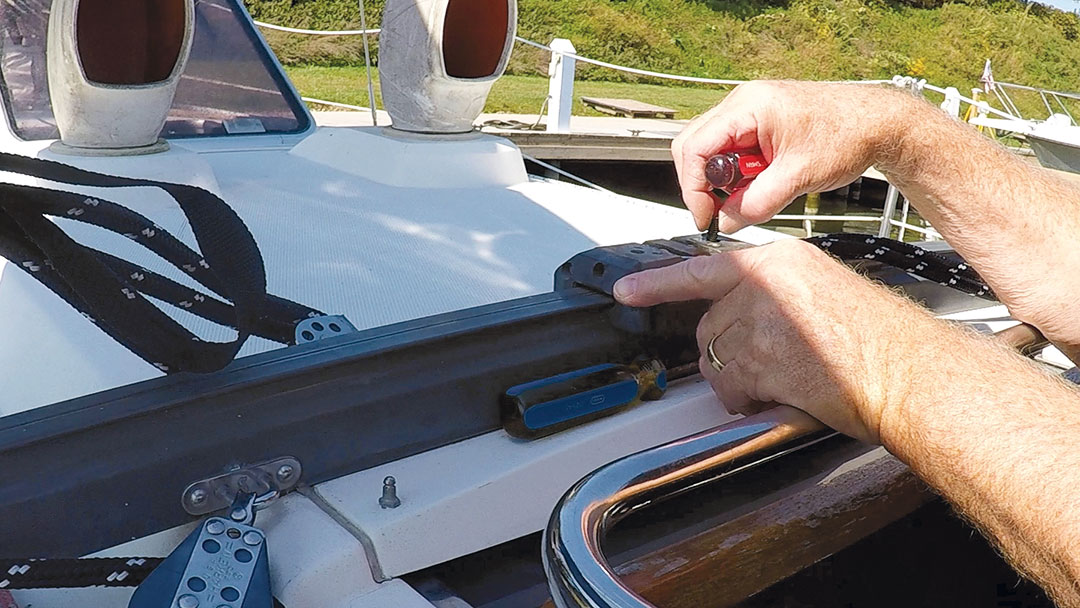
On my Harken traveler, it’s not immediately obvious how to access and remove the traveler car shackle. Initially I was inclined to remove the traveler car from the track; this would have been a mistake, because the old-style Harken traveler cars have loose ball bearings and require a special tool or a piece of track to remove the car without scattering them across the deck. Since other traveler cars may be similar, explore other options before removing a car from its track.
On the Harken car, the car shackle is held in place by a stainless steel rod captured inside the traveler car. Accessing the rod is deceptively simple. I started by removing the turning blocks to reveal two set screws. These screws prevent the rod from sliding out of the car. Once they were out, I inserted a screwdriver into a hole on the end of the car and pushed the rod out. This freed the shackle.
Before installing the new shackle, a small modification is necessary. The threaded side of the shackle must be drilled out to remove the threads. The unthreaded side of the shackle is 5/16-inch diameter; however, the screw threads reduce the hole’s diameter. A drill press makes quick work of this, but you could accomplish the same result by clamping the shackle to a work bench or a substitute and using a drill. In a real pinch, a rat tail file could also be used. You’re only shaving off a few thousandths of an inch here, and the hole should be enlarged no more than the diameter of the pin.
Changing out the mainsheet block shackle is straightforward: Unscrew the shackle pin and attach the new one. Note the attachment hole on the block will not accommodate captive pin shackles; the slightly larger diameter on the threaded side of a captive pin won’t fit through the hole on the fiddle block.
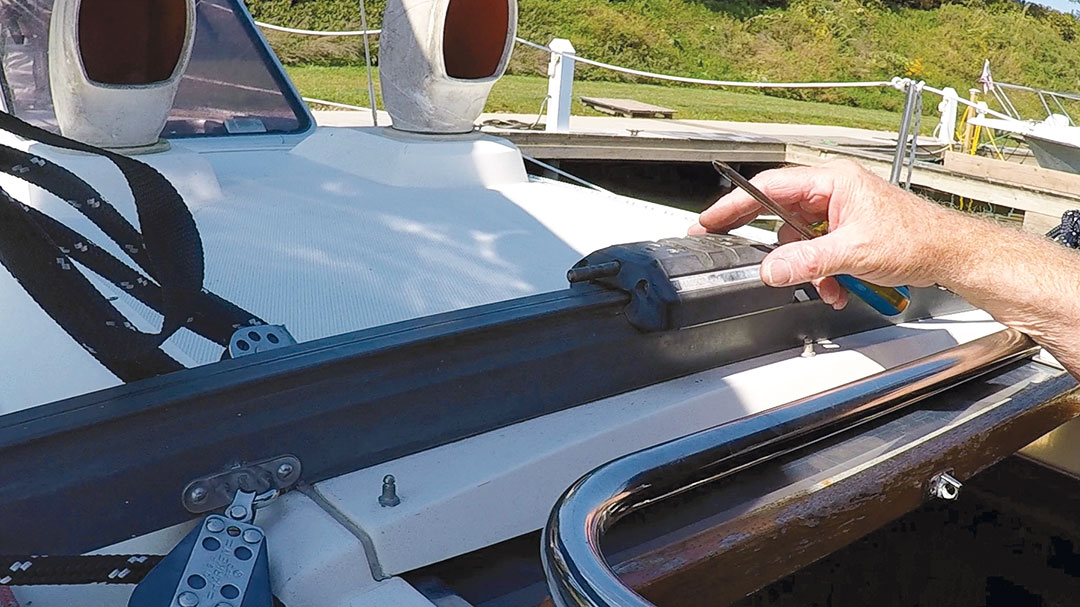
Reassemble the traveler first by inserting the shackle and pin; saltwater sailors in particular might want to apply a bit of LanoCote or Tef-Gel on the retaining rod for added protection here. Reinstall the set screws and reattach the turning blocks. Applying an anti-seize lubricant to the screw threads also will make future disassembly easier, and if you want extra security you can mouse the larger upper shackle to prevent it working loose.
This traveler is good to go for another 25 years.
Correlating Size and Strength
After I submitted this article, the Good Old Boat editor questioned my assertion that a percentage loss in shackle diameter due to erosion was proportionate to that shackle’s loss in strength.
“Are you sure about your numbers?” he asked.
I confidently replied, “Of course.” Then I dug deeper to be sure I was right.
Years of wear had measurably reduced the diameter of the shackle. The small shackle was nominally a 1/4-inch shackle that had worn from .2450 inches to .1750 inches. At its narrowest, my 1/4-inch shackle was now a bit smaller than a 3/16-inch shackle.
But what effect does the wear have on minimum breaking loads (MBL)? Is it indeed proportionate, as my back-of-the-napkin calculations indicated?
According to the Hayn Marine Rigging Products website, a standard 3/16-inch D shackle has a MBL of 3,300 pounds, and a 1/4-inch shackle has a MBL of 4,290 pounds. Stated another way, the smaller shackle has 77 percent of the strength of the larger shackle, or in the case of wear, a 23 percent loss in strength. The numbers were nearly proportionate; I was covered.
But I wondered if the same relationship would apply to larger shackles. Would a 25 percent reduction in size yield a 25 percent reduction strength? The short answer is, no. The larger the shackle, the greater the reduction in strength for a proportionate size reduction. For example, a 3/8-inch shackle is 25 percent smaller than a 1/2-inch shackle, but 36 percent less strong. As shackle size increases, the gap widens.
If I were a materials engineer, I could give a lengthy explanation, but the simple answer is that the strength of the shackle is related to the cross-sectional area, which is, of course, related to its diameter in a nonlinear way. One way to see the relationships between diameter, cross sectional area, and MBL is to compute correlations. The correlation between diameter and MBL is strong at .967; however, the correlation between MBL and cross-sectional area is stronger at a near perfect .991. These figures suggest calculating loss of strength is more accurate using cross-section area; however, changes in the diameter are a good proxy and yield results within a few percentage points. Not to mention, it is easier to calculate.
In addition to metal loss from erosion, other factors can contribute to strength reduction. Stressing metal with heat, excessive loads, bending, and impact can contribute to metal fatigue and failure. The discussion here is relevant to all metal-to-metal bearing surfaces, such as sheave axles, clevis pins, halyard shackles, and anchor chain. Even an apparently small reduction in diameter due to wear can lead to significant reductions in strength.
The takeaway? Do not ignore metal-to-metal bearing surfaces—inspect them regularly!
Other Shackles to Watch — Michael Robertson
The shackles that attach a mainsheet block to the traveler are under great loads and grind metal-to-metal, as Dave warns. But on many travelers, these shackles aren’t the only ones vulnerable to wear. On a boisterous sail aboard our 1978 Fuji 40 a few years ago, the traveler mounted to the track on our bridge deck suddenly ran to the leeward end of the track and stopped with a bang.
It was quickly apparent that the (very small) shackle that attaches the windward control line block to the car had failed under load. The shackle had worn over time where it attached to the car. We’d never before thought to inspect this critical connection point and realized we didn’t have a spare shackle aboard that was small enough to replace this one. Fortunately, we did have a small strop a friend had made from Spectra, and this did the trick for many days’ sailing.
Dave and his wife, Susan, look forward to another season sailing their Sabre 362, Second Star, on Lake Ontario, after COVID-19 delayed their plans for sailing out the St. Lawrence and embarking on a long-awaited cruise south. Optimistically, this means less pressure to complete the seemingly endless to-do list by June. Follow them at sv-secondstar.net.
Thank you to Sailrite Enterprises, Inc., for providing free access to back issues of Good Old Boat through intellectual property rights. Sailrite.com