It was time for a stronger autopilot, but the install presented interesting challenges.
Issue 133: July/Aug 2020
It was a June day, and a gale was blowing. I remember because I spent 18 hours hand-steering Violet Hour, our C&C Landfall 38, in big, breaking, following seas across British Columbia’s Hecate Strait. It was the day I learned that our wheel-mounted autopilot was not up to the task of steering our 19,000-pound boat in those conditions. It was the day I added “autopilot replacement” to the to-do list.
And that June day was not atypical. High-latitude coastal sailing in the Pacific Northwest often includes challenging waters on the outside and inside of Vancouver Island, running downwind in 25 knots with closely spaced, tidal-current-influenced waves. I needed a powerful autopilot I could have confidence in. And I knew that meant leaving the wheel and going below decks.
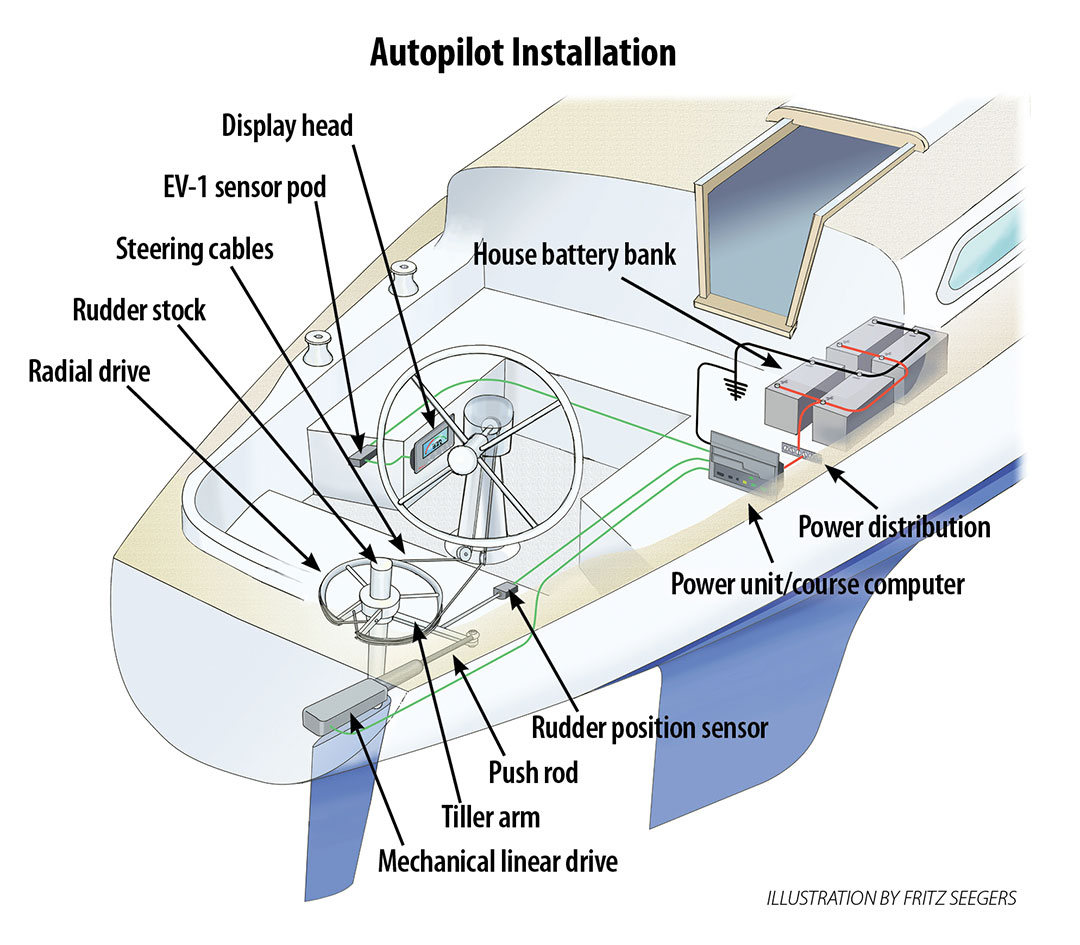
Installing a belowdecks autopilot means starting with considering where the autopilot push rod will connect to the boat’s steering system, and how it will connect. Next is deciding where the mechanical linear drive (the unit that includes the mounting foot, the motor, and the push rod) gets mounted. From there, wiring, electronics, and sensors follow.
Installing the Mechanicals
The primary mechanical considerations are attaching the autopilot drive’s push rod and mounting the drive unit. On my boat, both required thoughtful planning and precise fabrication.
On many belowdecks autopilot installations, the mechanical linear drive push rod is connected directly to a boat’s steering quadrant or radial drive. (A quadrant and radial drive serve the same function but are shaped differently. Because our boat’s steering system uses a radial drive, I’ll use that term in this article.)
Where possible, Edson strongly recommends attaching the autopilot push rod to the rudder stock, via a tiller arm. This is because many steering system radial drives are not designed for the strong forces an autopilot push rod can exert (650 pounds of peak thrust from the Raymarine Evolution autopilot that we bought).
Another advantage of mounting the autopilot push rod to the rudder stock via a tiller arm is redundancy. If that connection fails, I can still hand steer. And if the radial drive explodes, I can still steer using the autopilot. But if I attach the autopilot directly to the radial drive and the radial drive explodes, I have a serious, potentially life-threatening problem.
A typical tiller arm is cast bronze, about 10 inches long. It clamps around the rudder stock, above or below the radial drive. Our C&C has a pinched stern and very limited space around our Edson radial drive; attaching a tiller arm to our rudder stock would not be easy.
Making a difficult job more challenging was the fact that our Edson radial drive was already using nearly all of the exposed vertical space on our rudder stock, about 31/4 inches of the available 41/2 inches. This left me about 11/4 inches of exposed stock, and standard tiller arms are at least 13/4 inches tall.
I briefly considered drastic options, such as whether I could move the radial drive up or down to make more space (I couldn’t), and whether I could flip the radial drive or buy a new one with a slimmer profile. Indeed, a slimmer Edson radial drive or a Jefa radial drive with integrated tiller arm might have given me the space I needed. But, such a radial drive swap isn’t trivial, as it changes the height of the steering cable track, which would have required re-engineering the idler sheaves to avoid chafe, a substantial project.
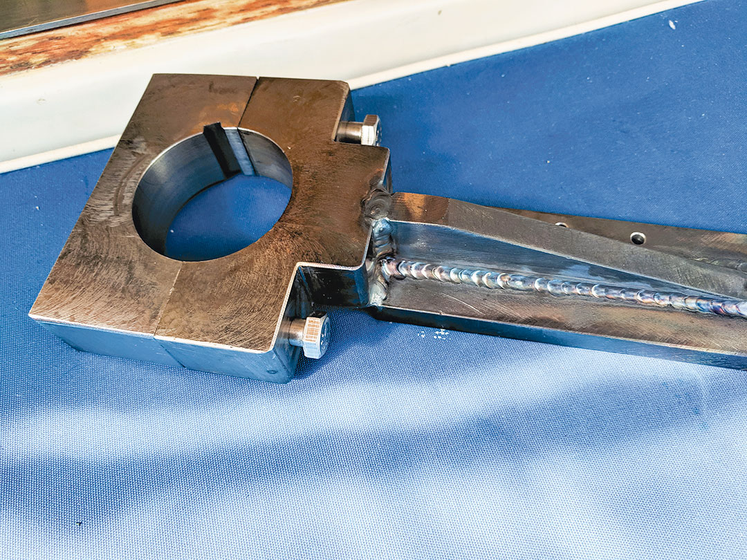
My solution was to have local machine shop fabricate a custom tiller arm. I sketched a design based on the idea of an offset tiller arm, which Buck Algonquin manufactures but not in a size that would meet my needs. An offset tiller arm clamps around the rudder post, and then the arm descends about an inch or two to clear the rim of my radial drive.
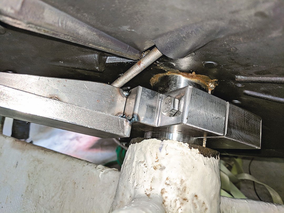
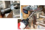
I found a machine shop that had fabricated tiller arms before. The steel tiller arm we designed features a welded-on arm. The center clamp is bored for a 23/8-inch rudder stock with a 1/4-inch keyway, and the clamp is secured with 3/8-inch bolts in tapped holes. While stainless steel would have been the ideal, the shop used A36 mild steel/structural steel, which it had on hand. To protect it from surface rust, I spray painted it with zinc chromate followed with a top coat of Rust-Oleum.
The keyway position in the new tiller arm must align with the keyway cut on the rudder stock so that the tiller arm meets the linear drive at a 90-degree angle.
Our boat’s stern is fairly narrow, and the Raymarine Evolution autopilot mechanical linear drive is a surprisingly large piece of equipment, about 3 feet long at full extension, and with a motor housing that is about 8 inches tall and 9 inches long. After measuring, I could see that there would barely be enough space to fit the mechanical linear drive in a transverse (port-starboard) configuration (which is common) and that doing so would have encroached on some of the storage space of our lazarette. My solution was to install the linear drive oriented fore-and-aft, pointing forward. This meant that the tiller arm had to extend from the stock at a 110-degree position (near perpendicular to the boat’s fore-aft line). This information helped me determine exactly where the keyway had to be on the tiller-arm clamp.
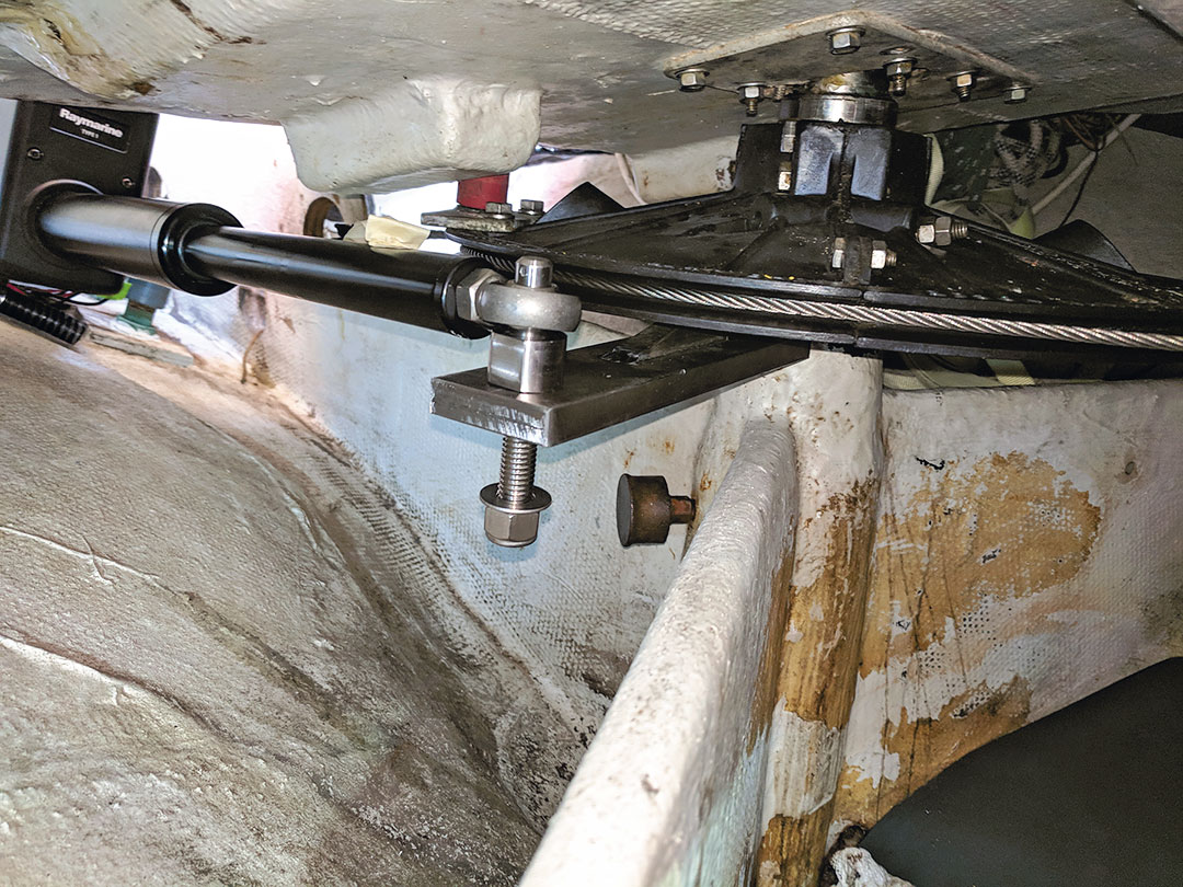
Next, two considerations helped me determine exactly how far away from the tiller arm and at what height I had to mount the motor end of the mechanical linear drive unit. First, I knew that the push rod had to align within 5 degrees of a flat plane with the tiller arm and must be the correct distance from the tiller arm to have full range of motion. These considerations meant that I ended up having very close install tolerances, only 3/8 to 1/2 inches in some places!
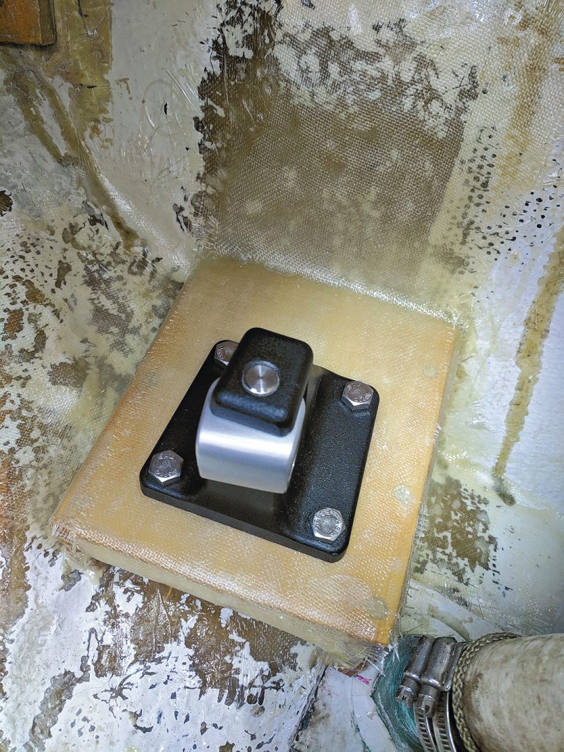
Next on the mechanicals list was mounting the linear drive unit. The motor end of the mechanical linear drive must be attached to a strong, secure part of the boat. Ideally, this would mean through-bolting it to an existing bulkhead or structural member. But rarely will there be an existing structural support right where it’s needed.
As is common in these installations, I needed to build a shelf, one strong enough to withstand all of the push/pull thrust forces that would be transferred to it. The shelf had to be large enough so that I could attach the 3 x 4-inch mounting foot of the mechanical linear drive, but also sized to fit in a pretty tight space at the stern.
I first made a cardboard prototype of how the shelf would fit into the hull. This process was fairly painstaking because the hull is a curved surface, and there were tricky angles to work out as well as ensuring proper height, distance, and clearance of the autopilot drive arm. I test-fit the drive arm on the cardboard shelf several times before building a shelf out of 3/4-inch plywood and fiberglass cloth. This shelf wasn’t up to the task, and I ended up redesigning it and replacing it with a much stronger version (Sidebar “Shelf 2.0”).
Installing the Electricals
With the mechanical part of the autopilot ready to go, four components of the system remained to be installed: the ACU-200, which is the power unit and brains of the system and is about the size of a proper dictionary; the EV-1 sensor pod, which contains the compass, gyro, and accelerometer and reports data from these instruments to the ACU-200; the P70s display head, which is the unit from which I’ll control the autopilot and therefore needs to be mounted near the helm for easy access; and the rudder position sensor, another piece of hardware that is mounted to the radial drive or tiller arm and which tells the system the rudder angle at any time.
Before choosing locations for each of these parts, I made a sketch of the system in the boat, showing possible locations. All of this hardware needs to be connected, and some of it connects via the included Raymarine SeaTalkng cables. But the cables are a fixed length, and they’re expensive, and I didn’t want to mount things too far apart and wind up having to order new cables. Additionally, the ACU-200 and EV-1 have specific installation requirements to consider.
The ACU-200 power unit had to be oriented vertically and installed close to the house batteries (or distribution point) to minimize voltage loss. Fortunately, I found a good spot only a few feet from the batteries and electrical panel. I mounted the unit and then started wiring the other components up to it once they were installed. To reduce interference that might happen via the ground, I connected a dedicated ground wire to this unit, as recommended.
The sensor pod must be installed on a level plane and pointing forward, but it can be mounted on a vertical or horizontal surface—and even upside down—as long as it is horizontally level. Fortunately, it can be rotated 360 degrees on its mounting case, so the bracket itself doesn’t necessarily need to point forward.
Because this pod couldn’t be mounted near sources of electromagnetic interference, I had to mount it away from the ship’s compass, VHF cables, and SSB wiring. I found a good spot inside our cockpit coaming. It was a difficult place to access, but the provided paper template helped with drilling the pilot holes for the bracket, and I used a bubble level to check that it was in a plane with the water (make sure your boat itself is level before doing this).
I used an existing, unused instrument hole in our cockpit to mount the display head and then only had to connect it with the provided cable. Once the install was complete, I used the display head to calibrate and set up the autopilot. Most of that I could do at the dock, but the compass calibration I had to do underway.
The rudder position sensor had to be installed below, near the mechanical linear drive and the rudder stock. Just as with the mechanical linear drive, the rudder position sensor’s arm needs to be at 90 degrees to the tiller arm, and in a level plane. Additionally, the arm needs to attach at a 5.5-inch radius from the center of the rudder stock. Typically, it’s easiest to attach this sensor to a point on the tiller arm, but it could also be attached to the radial drive (the rudder position sensor won’t exert significant loads, so the mount strength isn’t a big concern).I built a small plywood shelf and attached it to a bulkhead near the rudder stock using 90-degree elbow brackets. I carefully measured the distance from the shelf-mounted sensor to the tiller arm attachment point (with the rudder centered) and then cut a threaded rod to length.
The Outcome
After a year of testing our new autopilot, including sailing down the west coast of Vancouver Island in ocean waves, we’ve been thoroughly impressed with its performance. In heavy weather conditions it can steer as well as I can (or better) and provides a nice comfort zone; being able to leave the wheel in rough conditions makes reefing or other operations much easier. On average, it draws about 3 amps—not insignificant aboard our boat, but not a big electrical price to pay for the job it’s doing.
Although this was a time-consuming, difficult project, it was well worth doing it myself. Not only did I save thousands of dollars in installation costs, I know the system intimately and could easily diagnose any issues. Perhaps the only thing I regret is not upgrading our autopilot sooner!
Shelf 2.0
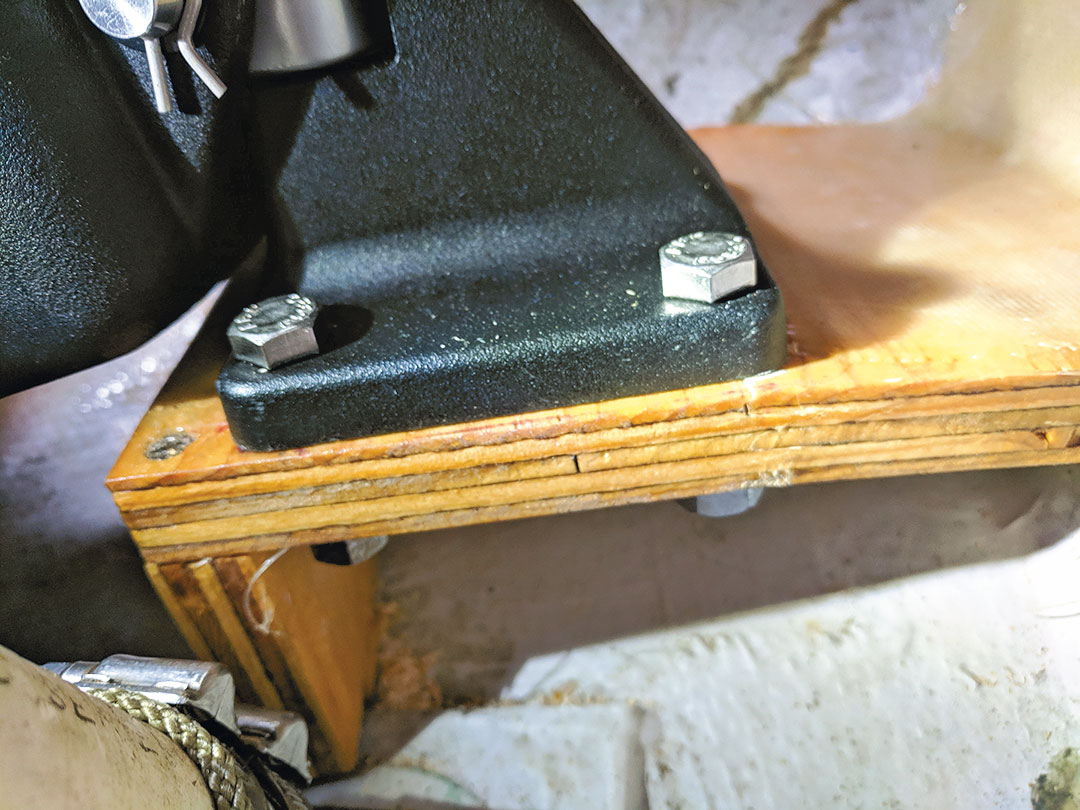
The first shelf I built to mount the linear drive unit failed pretty quickly during a couple of weeks of sea testing. A small crack appeared in the plywood, then I saw that under load it was flexing slightly, and the fiberglass was starting to delaminate from the hull. I knew the right decision was to start over and build a stronger design.
I reached out to the sailing community through online forums and I realized several mistakes I had made:
- My shelf support leg was oriented transverse to the direction of thrust, rather than in the same direction. This likely promoted flexing at that joint.
- My boat’s hull interior is painted, and epoxying to a painted or gelcoated surface is a recipe for poor adhesion. It’s important to sand or grind down to fiberglass first, even though this step makes a terrible mess and takes time, especially in a cramped space.
- It wasn’t enough to screw together a sturdy shelf and then attach that to the hull with fiberglass tabbing. I needed to encase the entire shelf structure in fiberglass and make it one with the hull. It’s better to think of the plywood as simply a core material.
I built Shelf 2.0 from 5/8-inch marine plywood and a much heavier layup of fiberglass. I also used a better design, supporting it with two legs oriented in the same direction as the thrust. The legs were glued to the platform with West System G/flex and then screwed together. Next I laid a fillet of epoxy thickened with colloidal silica along the inside of the joint (underside of the shelf), as increasing the radius of a joint improves strength. On top of that I layered 6-ounce, flat-weave fiberglass cloth to cover the underside of the shelf.
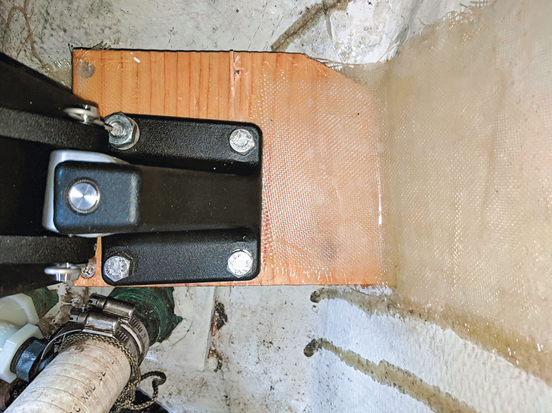
For bonding to the hull, I spread more West System G/flex along the plywood edges that would contact the hull. G/flex is a strong, flexible, peanut-butter consistency epoxy. I chose G/flex because several people online suggested that my shelf not have hard contact points with the hull, because hull flex could eventually affect the shelf.
Next, I laid up about seven layers of 6-ounce, flat-weave fiberglass cloth of increasing sizes across the shelf. The entire shelf was encased and overlapped onto the hull by 6 to 8 inches.
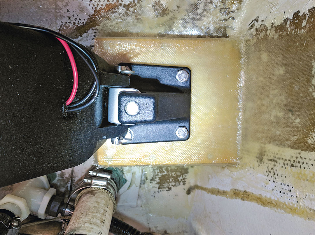
After leaving the shelf to cure for more than 24 hours, I test-fit the mechanical linear drive again and drilled the four through-bolt holes for the base. After attaching the push-rod end to the tiller arm, I was relieved and elated to find that everything had adequate clearance and proper range of motion.
Fabrication Considerations
The keyway cut in Patrick’s boat’s rudder stock was sufficient enough to use to align the keyway in his fabricated tiller arm. But not all rudder stocks have a keyway that’s long enough to do this.
If that’s the case, you have to come up with another way to attach the tiller arm to the rudder stock securely enough to withstand the considerable forces generated by the autopilot. It’s imperative not to take the easy way out and depend only on the clamping action of the tiller arm to the rudder stock to do this job. It will not be strong enough. Many standard tiller arms come with set screws to help secure the tiller arm to the rudder stock. These often work well on powerboats but can fail when subjected to the loads on a sailboat’s steering system in heavy weather.
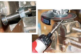
One way to make this attachment more secure (again, if the keyway is insufficient) is to through bolt the tiller arm through the rudder stock. After aligning the tiller arm to the drive unit, tighten the clamp bolts so the tiller arm will not slip on the rudder stock. Drill a clear hole through both sides of the clamp and the rudder stock. Use a stainless steel through bolt at least 3/8-inch diameter and secure it with a locking nut.
A brand-new cobalt bit will make this job easier; a battery-powered hand drill will make this job safer. But this is still a challenging job in what is usually a very tight space, and precision is required.
Regarding the shelf built to hold the linear drive unit, a stronger alternative to the 6-ounce, flat-weave cloth Patrick used would be double bias (DB) cloth. Though more difficult to work with, DB, which comes in 12- and 17-ounce cloth, has a more complex weave that provides more bonding surface area for the epoxy or resin, resulting in a stronger, stiffer laminate assembly.
Windvane vs. Electric
I did pause to consider replacing our inadequate autopilot with a windvane. We’re a low-electrical-usage boat, and minimizing fancy electronics (which are expensive and prone to eventual breakage) holds appeal. And being purely mechanical, a windvane is easier to repair than electronics, and could potentially be used as a back-up rudder. The price is about the same as a belowdecks autopilot (about 4-5 boat bucks, not including labor costs) and the install time is probably in the ballpark.
But a vane adds a giant appendage to the stern, extends the boat’s length (increasing moorage costs at some marinas), and can be tricky to adjust in rapidly changing conditions like we commonly sail in.
Ultimately, I decided a windvane is a great choice for crossing oceans, but that’s not what we need self-steering for. We need it for passages of about 12 to 24 hours for periods during which the waves make it too tiring to hand steer for long, or for brief periods when reefing, and for convenience when motoring.
Patrick Davin is a certified beer judge, cruising the Pacific Northwest with his wife, Natalie, aboard Violet Hour, their 1984 C&C Landfall 38. He writes about their adventures at www.svviolethour.com. His March 31 post about life on the hook during the time of COVID-19 is worth a read.
Thank you to Sailrite Enterprises, Inc., for providing free access to back issues of Good Old Boat through intellectual property rights. Sailrite.com