Worry about a bobstay failure inspires a rigging and anchor locker redesign.
Issue 139: July/Aug 2021
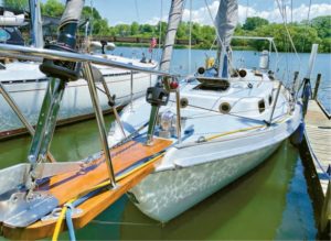
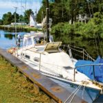
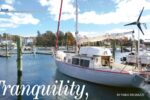
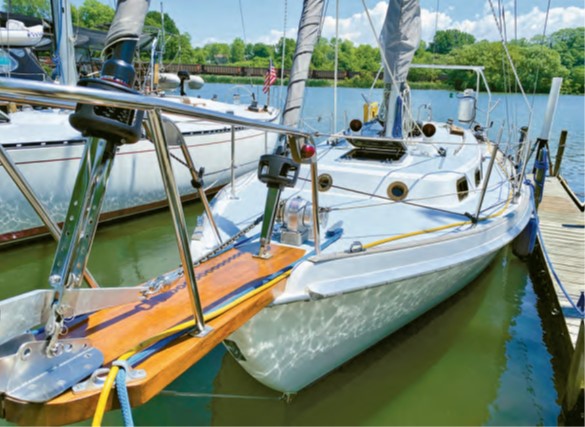
Over the years, I’ve come to know my 1978 Allied Seawind II pretty well. Yet, that part of my boat from the anchor locker forward remained a mystery. It’s a critical area, where the bobstay, forestay, and staysail all attach to the hull. Some of these attachment points were hidden from view, and I’d heard stories of bobstay failures on sisterships. I decided to explore, and what I uncovered was scary.
Our boat, named Sea Wind, is one of just nine cutter rigs of the 129 Allied Seawind MkIIs produced. Perhaps because so few cutters were built, Allied did not customize the deck mold to accommodate a cutter rig. Instead, they moved the mainmast aft, did away with the mizzen mast, and added hardware for a staysail. In doing so, Seawind built in a few problems, perhaps a result of over-engineering.
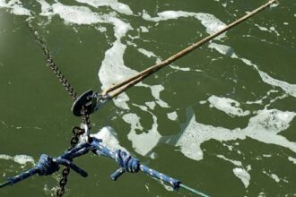
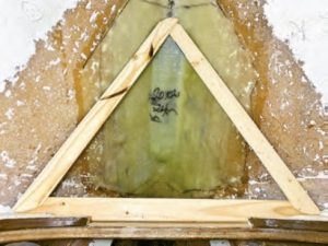
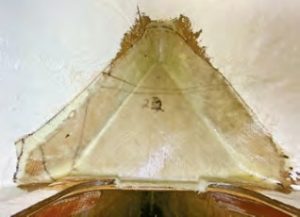
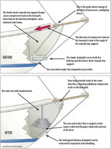
The staysail stay is attached to the bowsprit, aft of the yankee stay (forestay). Below-decks support for the staysail stay comes from a short length of 1 x 19 rigging wire that’s attached directly beneath the topsides fitting, then angles aft and down to attach to the same chainplate that protrudes from the hull to serve the bobstay. The entire interior part of the bobstay’s portion of this chainplate, as well as the base of the staysail’s attachment point, is encapsulated in a solid block of resin that forms the floor of the rode locker.
This design has worked for decades, but it’s not the most elegant way to go in terms of transferring rig loads. (Unnecessarily angling the below-deck support for the staysail stay results in a multiplication of forces and introduces additional compressive forces on the bowsprit.) Nor is it the greatest design when it comes to accessibility to the chainplate or practical use of the anchor locker.

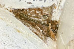
Encapsulating the shared chainplate in a big chunk of resin prevented me from being able to remove it for inspection and re-bedding. This is especially important given its location. One side of this chainplate lived in a perpetually damp anchor locker, the other side protruded from the hull right above the waterline. Then there was the oxygen deprivation of the resin-encap¬sulated portion of the fitting and the dangers of crevice corrosion at the intersections. Not good!
Also, the rigging for the staysail stay passed right through the middle of the anchor locker. This caused the anchor chain to foul while deploying and to awkwardly pile up when retrieving. And, I knew that chafing of the support wire would surely lead to malfunction at the worst possible time.
This past winter was the perfect time to dig in and revamp.
The Bobstay
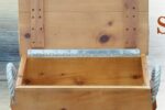
I accessed the rode locker from down below, via a large hatch at the head of the V-berth. I emptied the locker of chain and had full view of the solid-resin rode locker floor, from which a fitting protruded. After more than 40 years, I knew the clock was ticking on whatever was encapsulated that I could not see.
I used a multi-tool, hammer, and chisel to bash and chip my way through the resin. After many hours spent with my body awkwardly positioned in the anchor locker hatch opening, I had cleared away down to the hull laminate and I was able to remove the chainplate.
Rust and corrosion were forming on both the larger portion of the chainplate that served the bobstay, as well as the smaller section where the staysail stay was attached. I imagine it would have been much worse had Sea Wind not been a freshwater boat since she was built in 1978.
At this point, I was committed to redesigning the anchor locker and the bobstay and staysail stay supports to be stronger as a whole and to allow for easy inspection and future servicing. Nothing would be hidden in resin.
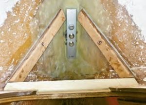
After the demolition, I prepped the inside of the hull, where the bobstay chainplate fitting passes through, using 80-grit paper on a 5-inch orbital sander. I hand-sanded where the tool wouldn’t reach. Then I epoxied in ½-inch G-10 fiberglass plates, which I had laminated and shaped into a wedge that fit the bow.
After these pieces were set, I laid up four layers of 24-ounce biaxial stitched glass of increasing sizes over the area using a chip brush and a roller. In the end, I’d created a stable and very strong, flat area for the new bobstay fitting backing plate. I used West System epoxy and a combination of their 404 and 406 thickeners for all aspects of the project.
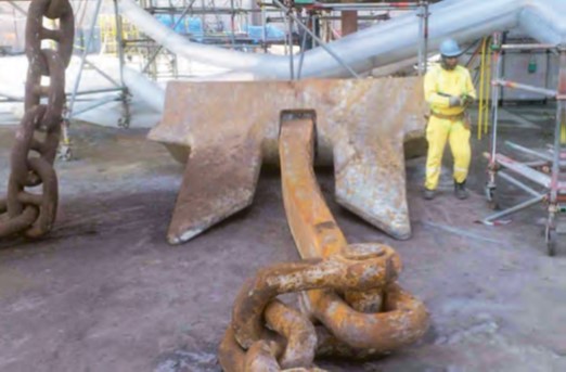
I ordered the new fittings from Spartan Marine in Maine. I spoke to John multiple times, and he was incredibly helpful. It turns out that the bronze bobstay fitting that they cast as a Cape Dory replacement fits the Allied Seawind hull shape perfectly. They offer bobstay kits, which include three 1/2-inch bolts, nylon lock nuts, and a pre-drilled aluminum backing plate.
After installing the new bobstay chainplate (which looks as beautiful as it is strong), it was on to the next modification.
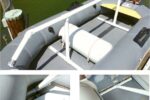
The Anchor Locker
I had to design a new anchor locker floor that could support roughly 270 pounds of 3/8-inch chain rode. The old locker did a poor job of draining any water and muck the anchor chain ferried aboard—and what it was able to drain went aft into the forward part of the bilge. This design spells disaster for the long-term integrity of some of the structural members of the boat, including both oak mast compression posts (a story for another day).
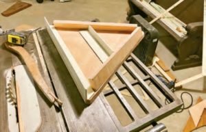
I used a hot glue gun and ripped-down strips of a 2 x 4 to make the template for the 3/4-inch marine plywood floor. To support the floor, I epoxied two pieces of the same 3/4-inch plywood in place on the port and starboard hull, and a rear piece of 1/4-inch fiberglass angle stock to the bulkhead.
Additionally, I epoxied a portion of the angle stock to the bottom of the 3/4-inch plywood floor, cutting the ends at an angle to rest on the plywood laminated on both sides of the hull. This addition to the underside of the floor not only adds stiffness but additional compression strength by pushing out on the sides of the hull, distributing the chain’s weight evenly. During the install, I applied thickened epoxy fillets to every inside corner.
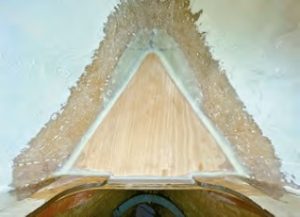
With the new triangular plywood floor glued in place, it seemed as though there was an end in sight. I laid up two layers of 24-ounce biaxial stitched fiberglass over the floor and up the sides of the hull and bulkhead. From there, I sanded back the rough edges and finally prepped the area with the random orbital sander and 220-grit paper. I used acetone and a stainless steel wire brush to remove the amine blush from the textured surface of the cured epoxy. This glass work further increased the stiffness and enhanced the abrasion resistance of the plywood floor. I coated everything with a two-part urethane for hardness and abrasion resistance.
The new floor falls forward about 3 inches over 2-1/2 feet, and the height of the floor is roughly the same as the original. It has a greater surface area, and the chain has more room to pile unimpeded. At the forward end of the locker floor, I drilled two drain holes through the hull, 18 inches above the waterline. Depending on the sea state, water occasionally enters here but drains back out. I am considering adding two small clamshell vents facing aft to minimize water ingress.
cloth over the plywood floor.
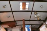
One of my primary objectives at the start was gaining permanent access to the bobstay chainplate so that it can be periodically removed, inspected, and rebedded. It may seem like the nuts on the interior of the hull, beneath the new glassed-in anchor locker floor, are impossible to get to, but it’s quite the opposite. I came up with the solution of cutting a hole in the anchor locker bulkhead, beneath the level of the anchor locker floor and also beneath the level of the V-berth. Now, lying on the V-berth, it’s an easy reach through the V-berth hatch and forward to the nuts. I just have to be careful not to drop the wrench or a nut!
The Staysail Stay
Next I had to design a new way to support the staysail stay below decks. I went back and forth about this part of the project more times than I can count. Eventually, I decided to use another Spartan Marine bobstay fitting, modified to fit the application.
The company agreed to sell me a “blank” fitting in which no mounting holes were drilled. I sanded off the radius on the fitting to make a flat spot and then made another flat spot in the hull where I would place the fitting using the same method and materials I used for the bobstay fitting. I drilled four 3/8-inch holes in the flat reinforced part of the hull and then made a 316 stainless steel backing plate for the hull exterior.
The location of the new fitting allows the forces imparted by the staysail stay to continue in the same direction, all the way to the hull. This reduces the ultimate force on the fitting and eliminates the additional compressive force on the bowsprit.
To connect the new hull fitting to the underside of the staysail stay bowsprit fitting, I made two 3/16-inch-thick tangs. At the ends of the tangs, I drilled 1/2-inch holes. The distance between these holes is 1/16-inch less than the center-to-center distance between the two fittings. This made it harder to attach the tangs, but pre-tensioned the chainplate system to prevent shock-loading.
This project required a lot of forethought, time, surgery, and boat yoga. But it’s been more than worth it, not only for the new and improved anchor locker and clean access to the two stays’ chainplates, but for my peace of mind.
Parker Misko is a young Pennsylvania native with a love for old boats. He has spent most of his life restoring Queen Anne and Victorian homes as well as partnering with his family’s HVAC business. He serendipitously found his way into sailing after hearing stories of his dad crewing on boats when he was younger. His first boat was a Balboa 20, on which he learned to sail on a local lake. After just a year, he purchased Sea Wind, an Allied Seawind 32, and has spent the last five years restoring and upgrading in preparation for living aboard full-time and bluewater cruising with his partner, Katy.
Thank you to Sailrite Enterprises, Inc., for providing free access to back issues of Good Old Boat through intellectual property rights. Sailrite.com