This is further technical information about purchasing, installing, and powering AIS devices from the article in the July 2015 issue.
Entr’acte’s navigation system consists of two identical chart plotters (nav station/cockpit), with charts (SD Card) for our current area. These plotters are hard-wired via NMEA 0183 to a Vesper XB-8000 AIS transponder and antenna splitter. The computer, running Open CPN, is used mainly for critical pre-voyage planning. Because of the power draw (3+ amps), we seldom use the computer for active navigation at sea. The iPad running SEAiq Free was originally our backup, but since the WiFi connectivity with our transponder has proved so easy, it now serves as an ancillary plotter when we are following numerous AIS targets and need a larger screen. The iPad also displays AtoNs where the Garmin plotter does not. The above system is very simple and cost-effective and — despite the limitation of the plotter — we are ecstatic with the results.
Transponder upgrade After thoroughly researching the available “black box” units, we settled on the Class B Vesper XB-8000 when we installed a new AIS aboard Entre’acte. With built-in GPS and WiFi transmitters, it was advertised to “connect to almost anything.” The installation of the 8000 and antenna splitter took less than an hour from box to first contact.
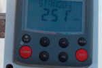
Power draw An important factor in choosing any electronic device is power draw. I will gladly pay more for a device that draws less power because, in the long run, it is far less expensive to reduce consumption than to produce amps. Our original AIS receiver, coupled with an antenna splitter and chart plotter, drew only .4 amps as opposed to almost 4 amps if the we used the computer in place of the plotter. Our new Vesper XB-8000, antenna splitter, and plotter transmitting AIS and WiFi draw only 1 amp, or .8 amp if we dim the screen a bit.
WiFi wizardry The latest onboard development is the inter-connectivity of the charting program to ancillary devices (computer/tablet/smart phone) via WiFi. I was skeptical. Dealing with Internet aboard is never simple, especially in foreign countries. Until worldwide Internet connectivity becomes as available, reliable, and stable as a GPS signal, I do not consider any device or software to be a proper navigation instrument if it requires “Internet connectivity” to function. However, this is different and, despite my initial reservations, it has real practical uses.
WiFi connectivity does not involve the Internet. WiFi means that the unit contains a built-in transmitter that creates its own local WiFi network on your boat. I downloaded and installed the pertinent apps on my computer and iPad. Yes, I did need Internet access, but only to download the apps. I opened the apps, entered a few numbers (listed in the installation manual) into the preferences boxes, turned on my transponder, activated the WiFi on my computer and iPad, and instantly the target alarm sounded.
I was truly impressed. Not because it worked but that it worked, and continues to work, seamlessly. Before my cockpit plotter had achieved a fix, my three charting programs — Open CPN (computer), SEAiq and iNavx (iPad) — connected wirelessly to my transponder without any fuss. Both devices were receiving GPS position information for navigation and all pertinent information relative to all AIS targets within my effective receiving range — more than 40 of them. WiFi connectivity has proven faster, easier, more reliable, and far less problematic than USB connections: no seeking out Internet hot spots, no fees, no forest of cables, no extra devices, and no fighting with com ports! Our Vesper will supply WiFi sufficient for five devices.
Before you buy Before you purchase any AIS unit, ancillary equipment (MOB device), or new chart plotter, consider your needs for the present and foreseeable future:
- Will the unit receive Class A and B ship targets?
- Will the unit receive AtoN (Aid to Navigation) signals?
- Will the unit receive MOB signals? If so, what will they look like?
- Will your present navigational system, computer, or tablet receive and process these same signals either by NMEA (0183/2000) or WiFi?
- Will your GPS plotter unit read and process the signals you require?
- What is the maximum safety-alert zone possible on the unit (program)?
When shopping for a new GPS unit or software, these are important considerations, but as daunting as this seems, it’s simple now that you know the questions to ask. Dealing with a knowledgeable vendor certainly helps. I have found the folks at Milltech Marine, DigitalYacht, and Vesper Marine to be outstanding in this regard.
Installation A GPS connection is essential. Since the purpose of AIS is to show a target’s location relative to your own vessel, any AIS device must have a GPS reference. Receive-only units usually acquire this reference via an NMEA 0183 or NMEA 2000 connection to an onboard GPS/chart plotter or via USB from a computer GPS unit. Class B transponders require and contain their own built-in GPS and cannot read GPS from any other source. They can, however, send GPS via NMEA/WiFi to other units, thereby providing a source of GPS backup.
Transponders and receivers can be purchased in stand-alone or black-box configurations. The easiest to install are the stand-alone units. Connect one to your battery and GPS, add a VHF antenna, and you’re in business.
If you have a dedicated chart plotter that accepts NMEA 0183 at a baud rate of 38,400 (NMEA high speed) you can save a bit of money and a lot of space by going the black-box route. These are ideal for those of us with small boats. They are much smaller and less expensive because they do not have screens or GPS receivers. The box is connected to your existing GPS unit(s) through the NMEA stream and, should you desire, connected to your computer’s charting program via USB or WiFi.
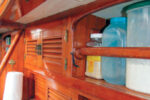
The connections are very simple. The black boxes fit almost anywhere. The wiring diagrams are color-coded and universal. Both of Entr’acte’s installations took less than an hour. If your chart plotter does not allow a 38,400 baud rate, it will most likely not receive AIS and you will need to upgrade to a newer unit. Check your manual or with the manufacturer. Our original receive-only unit was installed in an unused corner inside a locker in less than one hour.
VHF radios with built-in capability to receive AIS transmissions are also available. Contacts appear either on the radio’s screen or sent via NMEA to your mounted plotter and/or computer.

Wiring ins and outs
Never connect an “in” wire to another “in” wire. “In” always goes to “out” and “out” always goes to “in.” The NMEA “out” wire from the AIS connects to the NMEA “in” on the GPS plotter or computer. The NMEA “out” wire from the GPS connects to the NMEA “in” wire on the AIS. In the case of receive-only units, this connection is unused and left unconnected.
Connecting AIS to a chart plotter or computer via USB
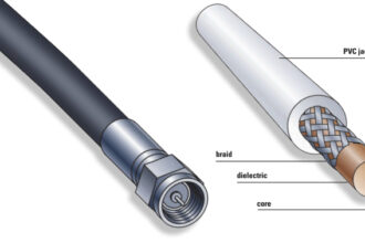
To connect your AIS device or cockpit plotter to a computer via USB will require the use of a serial-to-USB converter such as a Keyspan USA19H. This is a small, inexpensive device that has a 9-pin D-Sub connector (similar in appearance to an RS232 but with 9 pins input socket on one end and a standard USB output socket at the other.)
If your AIS device comes with a 9-pin RS 232 cable you need only plug it into the converter, attach a standard USB cable to the other end, and plug the USB cable into the computer. A Windows computer will, in most cases, automatically create a com port for your device. An Apple computer will connect right away. Enable your charting program to receive AIS and you will now see AIS data displayed on your computer.
For Windows computers, be careful to remember or, better, mark the actual USB port you plug the AIS into. Once the com port is created, some computers will only recognize your device from the USB port that was initially chosen. Plug into a different USB port and your device may not be recognized. This will not happen with Apple computers.
Notes: The diagram shows the AIS feeding targets to both the computer charting program and the GPS plotter. The GPS plotter sends position data to the computer via NMEA out (blue). However, if the computer charting program has its own dedicated hockey puck GPS, the GPS connection from the plotter (blue) to the D-Sub (brown) is not needed. If the AIS is a transponder, it will have its own GPS built in, so only one connection will be required between the AIS, plotter, and computer.
Making up a D-Sub connector
To connect a GPS plotter and AIS receiver to a computer, you will need to make an umbilical that will ultimately connect everything to your computer via USB.
Should you not have a proper RS 232 connector or wish to extend the one you have, it is very easy to make your own. Everything you need is readily available from Radio Shack and requires very little electronic skill.
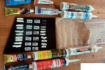
The D-Sub is a 9-pin connector and comes in either a male (pins) or female (socket) configuration depending on which one you need to connect to your USB/serial converter.
These connectors each come complete with the pins/sockets that attach to your wire. The connectors are advertised as solderless crimp fittings, but a dab of solder won’t hurt. The connectors have 9 sockets, each one numbered (very small) to avoid confusion.
Fortunately, you will only use three of the nine pins, numbers 2, 3, and 5.
Pin #2 is NMEA out from your AIS device, which connects to to your plotter or computer NMEA in.
Pin #3 is NMEA in from your GPS and AIS to your computer.
Pin #5 is ground.
Resources:
Radio Shack: www.radioshack.com
Part numbers:
- 9-Position (socket) Female D-Sub Connector: #276-1428
- 9-Position (pin) Male D-Sub Connector: #276-1427
- Connector hoodD-Sub Connector Hood : #276-1539