Well-known marine author Don Casey described how to remove the old engine from your good old boat. Now it’s time for the final exciting step …
Even though engine brochures generally provide all the measurements you need, it’s hard to reconcile them in three dimensions while the old engine is still in place. That’s why I delayed ordering the new engine until the old one was out and I could see exactly how a new one would fit.
To do this most effectively, I used a half sheet of foam insulation board, a razor knife, and a roll of duct tape to construct a rudimentary three-dimensional model. This took about 20 minutes, and it let me see exactly how much space there would be between the flywheel housing and the hull, between the top of the engine and the cockpit sole, between the alternator and a scupper hose.
I was able to move the foam “engine” easily to the limit of the stringers to evaluate clearance and access. An unplanned benefit of the foam engine was that it also helped me visualize the configuration of the new exhaust system and the routing of fuel lines and control cables. It also revealed, to my consternation, that the old rails weren’t parallel.
Now, confident that the real engine would hold no surprises, I gave my dealer the green light. A truck showed up at the yard exactly a week later with the new engine.
Fuel-tank issues
Don’t overlook the fuel tank. If the existing tank is galvanized – not uncommon for gasoline – you must replace it. A galvanized tank will flake particles of zinc into diesel fuel, blocking filters and injectors.
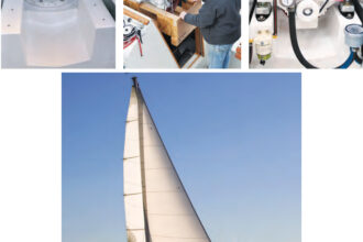
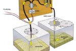
If the tank isn’t galvanized, but is captured by the engine, replacing it now might be a case of “a stitch in time.” Our fuel tank happened to be made of Monel metal, but I still wanted to pressure test it for leaks. This became easier when I discovered that a 1 1/4-inch threaded PVC plug was a perfect fit for the deck fill. I drilled a hole in the plug and installed a standard tire valve. I clamped short lengths of fuel hose to the outlet and vent fittings, then squeezed the hose closed with Vise-Grip pliers. A half-dozen strokes with a bicycle pump put the tank under light pressure, which I checked with a gauge. Never (I repeat, never) put more than about 3 pounds of pressure in the tank. When the tank was still under pressure the following day, I was satisfied that it was sound.
The next issue was 30 years of sludge. Having the tank professionally cleaned might have been a better option, but good access lured me into cleaning it myself. I drained the tank, then “scrubbed” the interior with rags stapled to a dowel. It turned out to be a tedious process, but eventually the rags came out clean.
If you convert a gasoline tank to diesel, you’ll need an additional fitting for the return of excess fuel. The neatest way to accomplish this is to drill a hole in the vent connection (remove it first, of course) and braze a hose barb over this hole. Return fuel is hot and should not go directly back to the engine, so do not put the return line barb on the pick-up fitting.
Finding the prop line
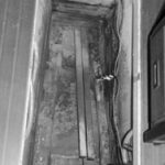
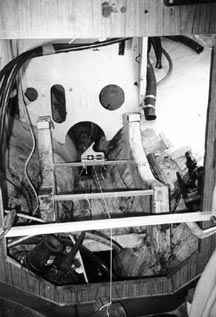
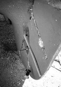
With the tank checked and cleaned, I turned my attention to the engine bed. The existing stringers were too tall, but it was essential to get them to the right height relative to the propshaft. I did this by stretching a string through the stern tube and across the engine space. Outside, I fastened the string to the rudder. Inside, I tied a heavy weight to the string and hung it over a length of cleat stock with a notch in the top surface to catch the string. This was clamped to either side of the engine hatch. By moving the notched board up and down, and from side to side (and with smaller adjustments of the outside attachment point) the string can be positioned in the center of the stern tube at both ends. This is the centerline of the propshaft, and it must also be the centerline of the transmission’s output shaft.
The engine and shaft must be in precise alignment.
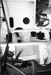
More to the immediate point, because the distance below the driveshaft centerline is the same for all four mounts on the Yanmar, this string also marks the correct incline for the engine stringers. To project this line onto the stringers, I cut two lengths of square stock to an interference fit between the stringers, wedged them in place just touching the string, then leveled them side to side with a bubble level. (I had already checked to make sure the boat had been blocked up level.) Tracing their top surfaces onto the stringers gave me the necessary two points to draw a line at the same height and incline as the shaft centerline.
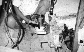
But the bottoms of the mounts aren’t at the same height as the shaft. On this particular engine, Yanmar specifies a position of from 0.87 to 1.42 inches below the shaft centerline. Reasoning that the mounts would compress with time, I chose the end of the range that gave me the highest stringers. Allowing a few extra thousandths for the planned overlay of glass sheathing, I drew a second line on the stringers 0.95 inch below the first. Using a circular saw and a clamped board as a guide, I cut each stringer on this second line. Because the rise of the hull interfered with the saw at the aft end, some handwork was required to complete the cuts.
The old rails were 1 1/2 inches too far apart in the front and nearly 3 inches too far apart in the back. I addressed this by sistering 1 1/2-inch thick white oak to the inside of the rails. Ideally, these pieces should have been wedge-shaped, but I couldn’t see any easy way to accomplish that, so I simply chamfered the top after installation to provide adequate clearance for the engine. I also added a couple of wooden gussets to the outside of the stringers, more to dampen vibration than to add strength. A couple of layers of fiberglass cloth over the rails and generously lapped onto the well-ground hull, completed the engine bed.
No heavy lifting
A simple plywood jig eliminates the need to move the heavy engine onto the bed until you are ready to bolt it in place. Make the jig from a flat piece of 1/2-inch plywood the length and width of the engine. With one end representing the mating surface of the drive flange, use a square to mark a centerline on the board. Measure from the flange end and the centerline to locate exactly the four holes for the flexible mounts, and drill them to the same diameter as the matching holes in the engine brackets.
Attach a perpendicular piece of plywood on the centerline at either end of the jig. These should be slightly longer than the distance between the bottom surface of the mount brackets on the engine and the centerline of the drive shaft – a dimension provided on the engine drawing. Mark this distance on centerlines extended (with a square) from the jig centerline and drill 1/4-inch holes at the marks. Saw into these two holes so you can slip them over the centering string.
Rerig the centering string, making sure it is in the center of the stern tube at both ends. Bolt the flexible mounts to the jig and set it on the engine bed, guiding the centering string through the saw cuts into the 1/4-inch alignment holes. Slide the jig fore and aft and side to side to position the mounts where you want them, then turn the adjusting nuts – the ones underneath – to raise or lower the jig until the centering string is in the center of both holes. Be sure you keep the jig level side to side and the mounts parallel to the centerline. Trace the mount holes onto the stringers, then remove the mounts from the jig and – without turning the adjusting nut – bolt them to the corresponding mount bracket on the engine. A word of caution here: even though the mounts look identical, there may be a difference in the elasticity between front and rear, so make sure you position them correctly on the jig to start with.
Drill the stringers for the lag screws that will hold the mounts in place, and you are ready to install the engine.
In with the new
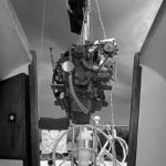
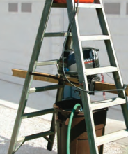
When the new engine arrived, the masts were still out of the boat, so I had the yard lift the engine with their boom truck and lower it through the companionway into the main cabin. Getting it under the cockpit was the reverse of dragging the old engine out, except that I couldn’t bear the thought of scraping that shiny paint off the bottom of the oil pan. I tacked a cleat stock stop across the end of a small rectangle of plywood and set the engine onto this “sled” for its short ride aft.
When the engine was in place, I installed the lag screws, snugging them down, then backing them off half a turn to allow some later lateral adjustment of the engine.
Prop and shaft
Prop configuration – diameter, pitch, number of blades, blade area, and so forth – is another subject altogether, but you do need to know the maximum prop diameter to determine the appropriate shaft diameter. The formula for propeller diameter is (632.7 x shaft horsepower0.2) / shaft RPM0.6, but as a practical matter, prop diameter on a sailboat is more often determined by clearance or acceptable drag. For example, the Yanmar I had selected, with a 2.61 reduction gear, is best mated to a 16-inch prop, but allowing the necessary tip clearance of around 15 percent of prop diameter, hull configuration limited me to a 15-inch prop. (I could have selected a lower reduction gear, but I preferred the slower shaft speeds.)
The rule of thumb for shaft diameter is one fourteenth of prop diameter. That is 1.07 inches for a 15-inch prop, which squares well with Yanmar’s recommendation of 1.1-inch shaft diameter for this engine. This assumes bronze or stainless steel, but you can safely reduce the diameter of a Monel or Aquamet shaft by 20 percent. Our existing Monel shaft could have done the job, but it was more important to me to have the engine as far forward as possible.
To determine the length of the new shaft, I temporarily bolted the shaft half of the new coupling to the drive flange. Inserting the old shaft into the stern tube to the mark I had made before extracting it, I was able to measure from the interior face of the flange to the end of the old shaft. I needed a shaft exactly 10 inches longer than the old one. But to isolate the prop electrically, I had decided to insert a flexible coupling in the drive train, which would move the coupling aft 1 inch.
The 7/8-inch diameter of the old shaft was marginal, so I decided to make the new one 1 inch in diameter, if I could do it without modifying the stern tube. A quick check of catalogs revealed that I could buy a 1-inch Cutless bearing with the same shell diameter as the 7/8-inch bearing. The prop shop had a 1-inch stuffing box that would fit my stern tube, priced at less than $50, complete with a new hose.
I ordered a 1-inch Aquamet 19 shaft, 9 inches longer than the old one, and had the prop shop fit and face the coupling. They also reconditioned the old prop and rebored it for the larger shaft. Prop shops often designate shaft length to the small end of the taper, so be careful that you tell them exactly how you arrived at your measurements. A drawing is a good idea.
With all the parts in hand, I installed the new Cutless bearing, quad-clamped the new stuffing box in place, inserted the new shaft, and installed the new flange.
The crowd roared
With the shaft flange just shy of the drive flange, I moved the shaft up and down to find the center position. Supporting it there, I checked for misalignment with a straightedge. None. I slid the shaft forward and the coupling mated with a satisfying thunk. The crowd roared, but it was the centerline string and the plywood jig that deserved all the glory.
I checked the space between the two halves of the coupling with a feeler gauge. The maximum gap was about 0.012. Not good enough.
The engine and shaft must be in precise alignment.
Yanmar specifies a maximum face runout of 0.008, so I tapped the forward mounts slightly to starboard and gave the adjusting nuts on those same mounts about a half turn. The maximum gap dropped to 0.005. Now it was good enough. The boat would likely change shape slightly when it went back in the water, and I would recheck the alignment then.
Finally, I separated the coupling and reassembled it with a flexible doughnut (Drivesaver) between the flanges.
Dripless packing
Because I find simplicity nearly always superior at sea, I decided against a mechanical shaft seal. But I was interested in trying dripless packing in hopes of minimizing how many times I would have to tighten the stuffing box.
Dripless packing turned out to be easy to install, captured on either end with rings of standard Teflon packing. The only drawback so far is the substantial cost.
Wiring and plumbing
It would have been easier to install the fuel and seawater filters and the coolant subtank while the engine compartment was empty, but I wasn’t sure of their exact locations until the engine was in place. The engine came with the subtank and a Racor fuel filter, and at the suggestion of Mike Muessel, president of Oldport Marine Services in Newport, R.I., who served as my technical advisor, I selected a Vetus above-the-waterline raw water filter.
The subtank came with its own hose, but the barb at the engine fill faced the wrong way. To keep the hose run as short and straight as possible, I unbolted the filler neck and turned it around, taking care not to damage the gasket.
The water connection should have been a snap – a 3/4-inch hose from the through-hull fitting to the filter, and a second hose from the filter to the engine. Inexplicably, however, the barb on the engine turned out to be 5/8 inch, so a hose adapter was required. Always make raw water connections with reinforced (suction) hose so it will not collapse if the through-hull or the filter become partially blocked. Double clamp all below-the-waterline connections.
Fuel hose (types A1 or A2) makes fuel connections as easy as water connections. The line from the tank to the engine is broken twice, once for the shut-off valve and again for the primary filter. The return line leads directly from the engine to the tank.
The most difficult connection is probably the exhaust. Waterlift mufflers have become nearly universal, but they must be installed properly or they have the potential to flood the engine. Guidance is widely available.
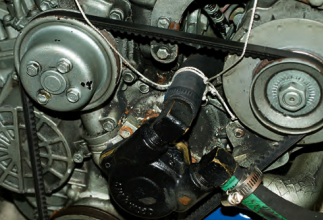
I elected to install a Vetus waterlift muffler, but because the bilge configuration prevented mounting it well below the mixing elbow, I used a galvanized nipple and a threaded coupling to raise the elbow. This provides increased resistance to backflooding and has the added benefit of raising the water injection connection above the waterline, eliminating the risk of water siphoning into the engine through the raw-water pump. A gooseneck muffler at the transom that takes the exhaust line right up to the underside of the deck before exiting the transom somewhat lower, should prevent following seas from forcing water back into the engine.
Single-lever control
Out in the cockpit, I installed a new single-lever engine control – the old engine had a separate shift and pull-up throttle. I used an old cable as a “scout” to determine the route and length of the new cables.
The cockpit was also the logical location of the new instrument panel, although the installation instructions cautioned against exposing it to the weather. Recessed enclosures are available, but in our cockpit there was no place to install one. The alternative was a custom teak frame with a gasketed acrylic cover.
I was disappointed to discover that the only instrument on the “instrument panel” was a tachometer. No oil gauge, no water-temperature gauge, no ammeter, and no engine-hours meter. Lights and alarms are certainly better at announcing a problem, but I find gauges very useful in heading off the kinds of problems that eventually sound an alarm. Gauges are on my shopping list.
The good news is, after you mount the panel, wiring it up is dead simple: connect one end of the furnished harness to the plugs hanging from the back of the panel, the other end to the plugs on the engine. That is it.
The only other electrical connections are the battery cable connections to the starter. If you are replacing a gasoline engine, be cognizant that the starting loads will be much higher for the diesel. Your existing battery cables are probably too small. How big they need to be depends on the current draw of the starter motor and the round-trip length of the cables. The appropriate cable size for our installation was 2/0. Don’t scrimp here. This will make the difference between starting and being dead in the water when your batteries are low.
Running the engine
Fill the engine and transmission with the specified oils. Make up a 50/50 mix of antifreeze, and fill the header tank and the subtank. Fill the fuel tank with fresh fuel and bleed the fuel system according to the engine-manual instructions. The only remaining requirement is a flow of cooling water.
In the yard, I disconnected the pick-up hose from its through-hull and stuffed it through a nearby 1 1/2 inch through-hull fitting for a (disconnected) cockpit scupper. Outside the boat, I supported a bucket against the hull and over the fitting, with the pick-up hose extending down into the bucket. A running garden hose secured to the bucket kept it full and overflowing. I also used the hose momentarily to prime the pickup line. If you don’t have a convenient through-hull, you can wedge the bucket next to the engine and let the bilge pump take care of the overflow.
To get oil to the engine before starting, it is always advisable to spin it with the starter for about 5 seconds while continuously pulling the kill knob to prevent starting. After this precaution, I turned on the key, hit the starter, and the engine fired, clattered for a moment, then settled into a satisfying purr. A look over the side confirmed that the cooling water was flowing through the engine and out of the exhaust. In fact, I was surprised at how much water the pump drew. When I increased the engine speed, the faucet had to be wide open for the garden hose to maintain a full bucket. Don’t let the water level drop below the pick-up hose or you will burn up the pump impeller.
Once in the water, you will need to check engine/shaft alignment one more time. Take the time to tweak it in as close to perfect as you can get it.
After a couple of engine hours, open the throttle all the way to see if your prop selection was correct. Ideally, the engine should just reach the maximum specified RPM. If it runs faster, you need more pitch. If you can’t reach maximum revolutions, less pitch is indicated. However, being slightly overpropped (too much pitch) does put more power into the water at cruising RPM, not altogether a bad thing.
Worth the effort?
Lower levels of irritation and worry are intrinsic benefits of a new engine, but installing it yourself offers other bonuses. There is, of course, the pocketful of money you will have saved. Doing it yourself lets you determine the level of workmanship. You can also expect a satisfying sense of accomplishment. But perhaps the biggest advantage is an immediate intimacy with the new engine. The knowledge of how all the components work together and what they need from you to keep working provides a matchless basis for a long and happy symbiosis.
Article taken from Good Old Boat magazine: Volume 3, Number 1, January/February 2000.