What started as a joke between sailing partners became a transformational DIY bow thruster project
Issue 149: March/April 2023
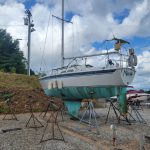
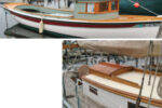
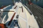
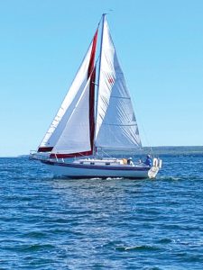
David Jolly and I are partners on Kindred Spirit, a 1985 Bayfield 32C that we bought in 2020. We’ve spent enough time on the boat to know that this is the boat for us. We love its cutter configuration, stability, and its double pole setup for jib on jib. Because it’s THE boat, and we’re not going to upgrade to the next best thing, it really motivates us to do a lot of work. We restored the teak and built a custom, vacuum- formed HDPE boot with poured-in blocking for the mast. We also added a rigid boom vang, Mack Pack, dockside air conditioner, and a new mainsail.
After all those upgrades, our little joke was, “Maybe a bow thruster.” It was funny at first, but as time went on, the idea became more attractive.
When we bought the boat, we noticed that a board was broken on the starboard side of the bowsprit. We had no idea why. But we found out, through our own experience of backing up, that reversing a full-length keel boat is no treat.
The previous owner probably whacked something when leaving port. The biggest challenge of sailing a Bayfield 32C is backing up, because the awful prop walk brings your bow to starboard, and the sailboat is difficult to control. It’s just the nature of the boat — once you’re sailing, there’s so much the sailboat can do.
With the type of sailing we do, from point to point, we’re in harbors a lot. Some docking situations are far from ideal, with boats in close proximity, and we really don’t want to put our boat or any other boat in peril. We just wanted to make our lives a lot easier. So we decided to install a bow thruster on our 32-footer. It seemed like a project we could take on ourselves to save thousands of dollars.
David and I work well together — our personalities, skills, and ways of thinking mesh well. David is a retired owner of a prosthetics company who restores classic cars on the side. My background is in home construction and professional walleye fishing.
With limited space on a 32-foot boat, the first thing we had to determine was if a bow thruster would fit. We wanted a through-hull, not an add-on under the hull, to reduce the chances of the thruster bumping something. Plus, if your bow thruster is properly designed with raised fairings that look like eyebrows, you reduce cavitation and drag on the boat.
Given the daunting task of cutting a huge hole in the hull of Kindred Spirit, we did a lot of research before we
started. After watching YouTube videos, we were shocked to see the ways people installed bow thrusters. We certainly learned what not to do. We read literature and technical data on bow thruster manufacturer websites and various forums before we made the decision to, if possible, install a through-hull Lewmar 140 TT 12-volt bow thruster.
We purchased the unit, plus a 6-inch Lewmar fiberglass thruster tube. Although now committed, we allowed for the possibility of returning the items based on the results of our confirmation of fit and location. Having the physical components in hand seemed like the best way to proceed.
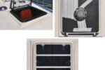
In order to see the amount of space we had to work with, we removed the blackwater tank — something that shocked a lot of Bayfield boat owners because it’s notoriously difficult to remove. Thankfully, removing the tank was possible. We discovered that we could take out four screws to remove the cabinet located aft of the tank, creating just enough wiggle room to pull out the tank. Of course, one project often leads to another. With the cabinet and tank removed, we decided it was the right time to replace the 35-year-old hoses and totally rebuild the head — a bonus project that will save us from dealing with bathroom issues down the road.
I credit David for coming up with a major breakthrough that helped us determine if the bow thruster would fit — an interior hull/bow section 3D model of Kindred Spirit and prototypes of the 6-inch tube and bow thruster unit. His model showed the space where the bow thruster potentially could be positioned, both below the surface of the water and from the bottom of the hull of the boat. From the model, we could determine how far back the bow thruster would fit and still leave space for the holding tank. We found out that we had only about an inch tolerance up, down, forward, and aft. We were also going to have to angle the thruster motor precisely so we could have access to service the motor while not having it protrude into the top of the front V-berth deck. So we needed a very accurate placement of the 6-inch thruster tube.
Another big breakthrough came when we confirmed the position of the bow thruster using rare earth magnets. With me on the outside of the hull and David on the inside, we pressed our magnets to the hull. The magnets locked into each other. Referring to the center hole locations projected onto the interior hull, I dragged the magnets to where we thought the bow thruster would go. On the inside of the boat, David’s magnet moved along with my magnet, matching the locations he identified through using the model.
Now we had both inside and outside proof that confirmed the manufacturer’s recommended tube location, and we knew that the interior modifications and access to the bow thruster motor and components would be possible. Before installing the thruster tube, we looked at a lot of installations on YouTube and saw people drilling holes, grinding gaps, and filling them in. It was crazy. We decided to break new ground and go a different route.
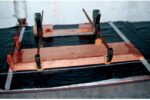
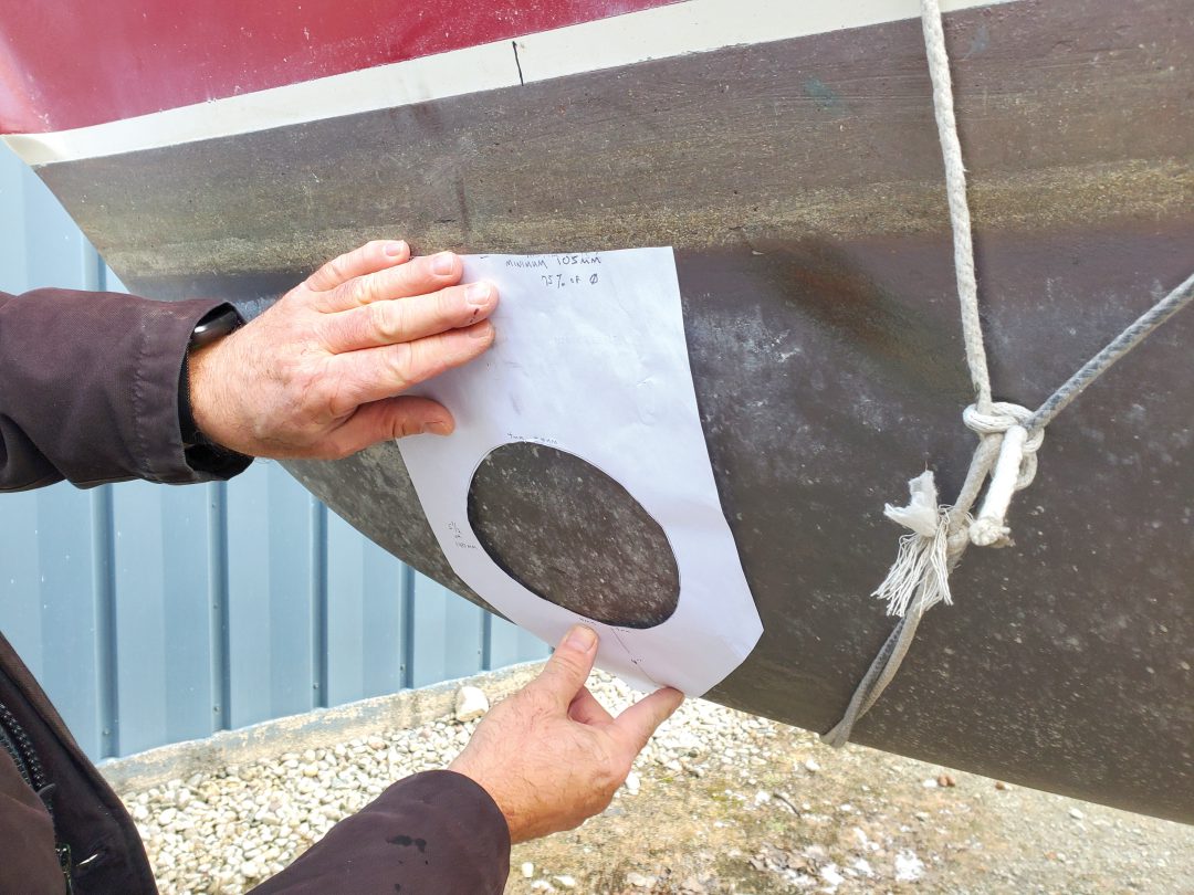
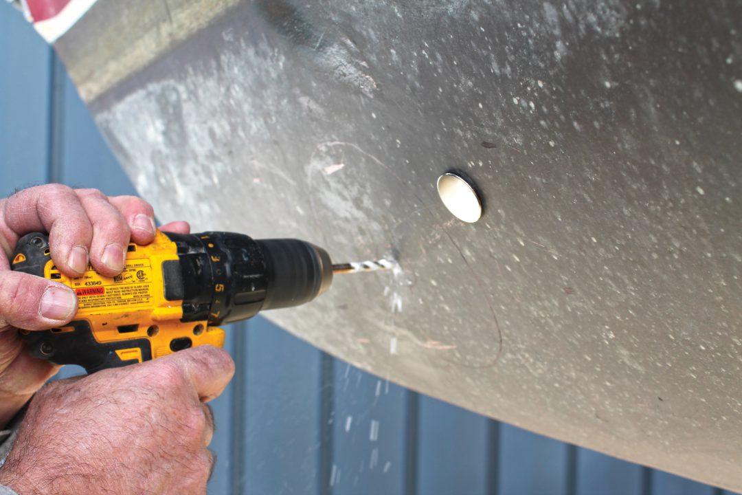
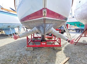
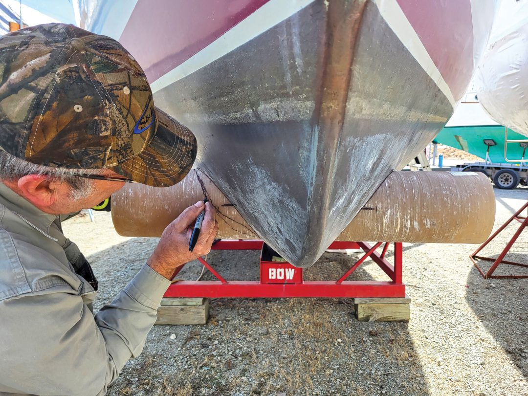
The shortest distance between two points is a straight line, and we knew where the through-hull center of the tube would be, thanks to the magnets. The hull angles wider toward the top and narrower at the bottom, creating a compound angle that forms a goose-egg-shaped hole. We had to look at the physics of having a hole parallel to the ground. We drilled two ¹/₄-inch holes in the center of the oval, one on each side of the hull, as determined by magnets, prototypes, and diagrams. Then we drilled a third hole in a 2 x 4 board and stood up the board next to the hull so its hole aligned with the first two holes. The 2 x 4 provided additional stability for the rod we were about to insert.
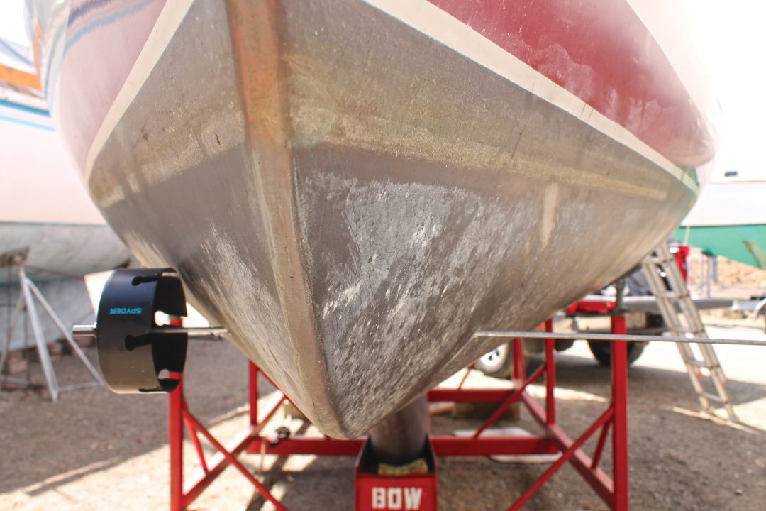
We bought a 6-inch carbide hole drill, removed the ¹/₄-inch drill bit, and fastened a ¹/₄-inch diameter, 36-inch-long rod instead. We then slid the rod through the two holes in the hull and the hole in the 2 x 4. Our theory was that the hole drill would have to follow the rod. We hadn’t seen anyone do this, but we knew in theory that it would work. We could only drill a short distance, so we cut out pieces of the hull as we went. Our drill bit had a maximum cut depth of 2 ³/₈ inches, but in retrospect, a hole saw with more cutting depth would have been helpful, as long as you do not cut the center reference hole out.
Once we had drilled and cut about halfway through the hull, we came back at the hole from the other side of the hull. It was important not to lose the center reference points. We were amazed by how thick the hull was — about an inch. Engineering in 1985 was based upon the supposition that more fiberglass was better. The Bayfield 32C is built like a tank.
Through patience and a lot of drilling, we finally accomplished our goal. We now had a 6-inch hole through Kindred Spirit’s hull, and it was a beauty!
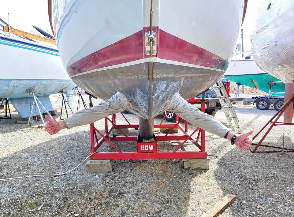
Drilling that 6-inch hole through the boat was the scariest part of the project. We were fully committed at that point. We held our breath as we slid the tube into the hole. It fit with less than ¹/₈-inch of tolerance around the tube.
I don’t want to make this seem like some gushy bruh moment, but what a moment! All our research and strategizing paid off. With a huge smile on my face, I thrust out my hand to shake David’s.
We stood there for a moment and looked at the hole we made — two sailors proud of having the ingenuity to pull this off. A bow thruster wasn’t a joking matter anymore; it was becoming a reality.
Once the tube was inserted, we confirmed the position of the tube and the angle of the thruster motor attached to it. This is where the fun with epoxy and fiberglass began.
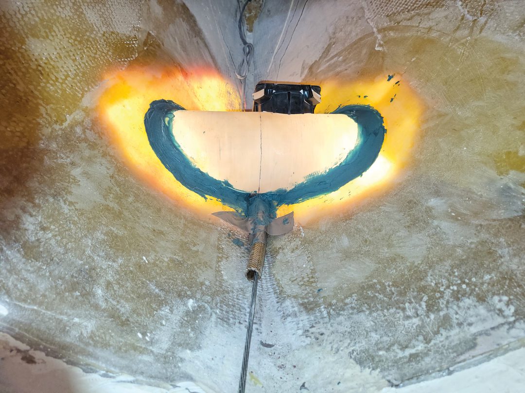
We performed the initial bonding of the thruster tube to the hull with West Marine G/flex 655 thickened epoxy. This worked perfectly in that it stayed put on the vertical surfaces. Before bonding the tube, we precut and bonded the thruster motor saddle to the tube.
The manufacturer instructions suggest doing this after the tube is fully externally and internally bonded. With our very critical fit and limited working space, we needed the saddle in place. We indexed the tube to maintain the saddle tilt while the external bonding occurred. We then internally placed a fiberglass gusset around the tube to provide a radiused transition for the fiberglass tabbing to follow. We bonded the tube to the hull with West System 105 Epoxy resin and several layers of biaxial fiberglass cloth. We protected the top of the saddle and included the fiberglass reinforcement around this structure.
Teamwork was helpful for David, who was wedged into the hull space area while I mixed, saturated, and handed off the materials as needed.
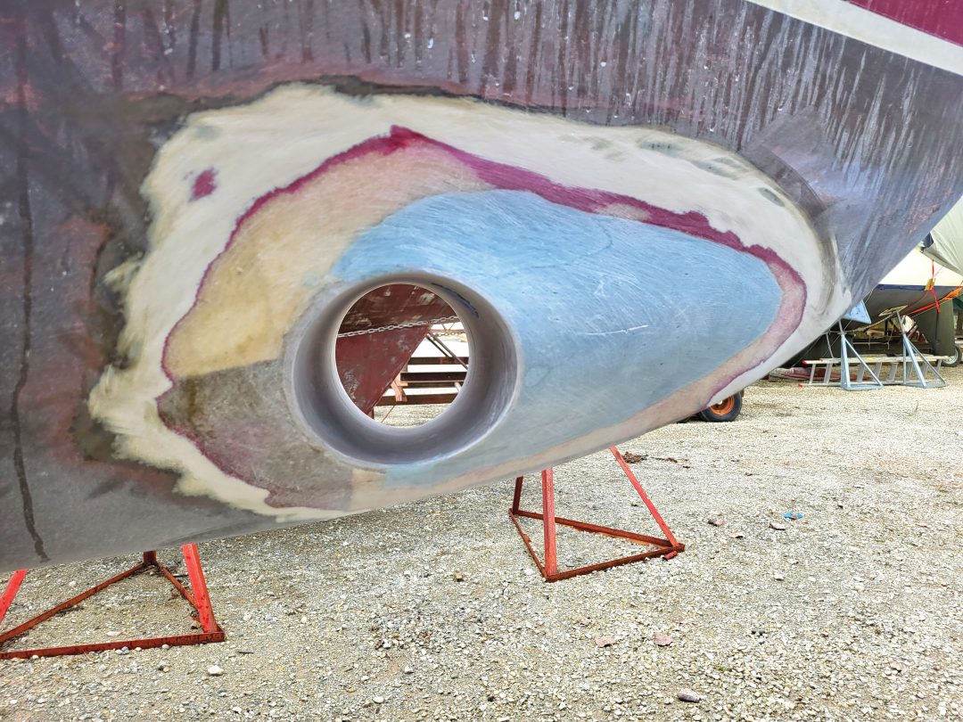
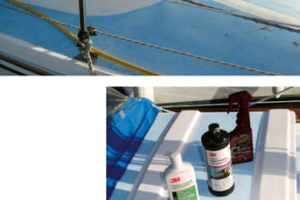
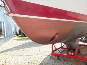
Next, we needed to flare the forward part of the hole with fiberglass to create an eyebrow. The eyebrow allows water to flow freely over the tube opening, reducing drag. The final exterior finishing consisted of fairing and sanding to the hull surface, then painting a barrier coat and a final bottom coat layer, including the inner surface of the thruster tube.
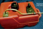
We purchased a third-party wireless control to operate the bow thruster at the helm, plus a portable control that we attached to a lanyard that you wear. Both the sailor at the helm and the one standing at the bow or elsewhere on the boat can operate the bow thruster using the wireless controls. It’s so nice to have a backup.
With our new bow thruster, Kindred Spirit is much easier to back up and launch, especially in windy or cramped conditions. Docking is much more pleasant, causing a lot less anxiety. And we really turn heads when the bow thruster spins the boat. Watching a boat pivot in place is a sight to see.
The entire project — bow thruster unit, resin, hatch, remote, parts, and pieces — cost us $2,367.90. Because we’re partners, we joke about getting everything at half price, so it cost me $1,183.95.
At the marina where we work on Kindred Spirit, there’s a sign that reads, “Sorry for what I said while docking the boat.” Sailors of full-keel sailboats under- stand the meaning behind this apology. Now, with a bow thruster on Kindred Spirit, we can back away from that statement as easily as we back away from the dock.
Bill Koehne and David Jolly met while volunteering at the local community theater and quickly became friends. As co-owners of Kindred Spirit, they enjoy bringing their 1985 Bayfield cutter to better-than-original condition and sailing the waters of Lake Michigan.
Thank you to Sailrite Enterprises, Inc., for providing free access to back issues of Good Old Boat through intellectual property rights. Sailrite.com