Where cast aluminum failed, mild steel became the material of choice
Issue 127: July/Aug 2019
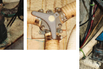
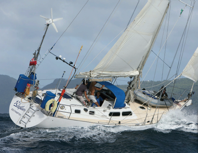
The cast-aluminum steering quadrant on Rhythm had been in use for approximately 15 years. When I removed and examined it in 2006 during a major refit, it looked perfectly sound. Three years later, we were sailing in a storm in the middle of the Tasman Sea when the port steering cable broke. The loose rudder slammed to port against the rudder stop, causing the quadrant to break apart. Luckily, we carried a spare quadrant and cables with which to effect repairs.
I’d never heard of a steering quadrant breaking to pieces, but after talking to several sailors, I learned that it has happened to others. Since that incident, I’ve had little faith in production steering quadrants. To keep costs down, most of them are cast in aluminum or some other alloy, and while cast metal is plenty hard, it has no give, is brittle, and is vulnerable to shock. Worse still, most steering quadrants have holes drilled in them for attaching accessories such as a rudder indicator or the autopilot ram. These holes significantly weaken the casting.
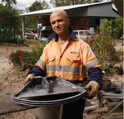
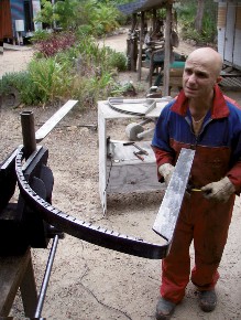
Now, I am not an engineer, but I do like to fabricate or improve things. And because I was recovering from a broken pelvis and eager to do something constructive after lying on my back for two months, I decided to fabricate and fit a stronger quadrant than the replacement then in use.
My goal was to fabricate a cheaper-but-better product using only basic tools and a welding set, with no machining. For this reason, I decided to use mild steel. The only challenge I could foresee was how to make the keyway that locks the quadrant to the 2-inch rudder stock.
Getting started
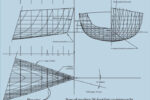
 I placed the old quadrant on a piece of ¾-inch plywood and drew a reasonably accurate outline. This would be my reference during fabrication. I’ll note that my outline included the wire channels on the arc of the quadrant’s frame, as they would be welded on later and increase the overall size.
Angle-iron frame
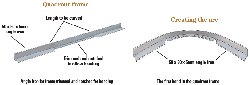
For the framework of the new quadrant, I used 50 x 50 x 5mm-thick angle iron. I found it best to start with a slightly longer section than required and trim it to size later. I marked the center of the bar, which would also be the center of the quadrant’s arc, or angled section. From this centerline, using the outline as my guide, I measured left and right to the points where the angle iron was to be bent to give it a triangular shape.
To make it possible to form the arc and bend the corners, I cut and trimmed the sections as shown in the drawing “Quadrant frame,” above.
Creating the arc
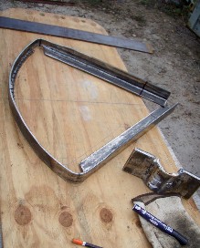
To form the arc, I bent the prepared angle iron over an old steel boiler, checking against the outline drawing as I went. An anvil or similar robust former could be used. The result was as shown in “Creating the arc,” above.
Forming the bends
Once I’d formed the arc, I bent the corners to complete the triangular shape of the quadrant. First, I ground away a 2.5-inch section of “teeth” from the two bend corners. (Adding the strongback plate later on restored the strength to the assembly.)
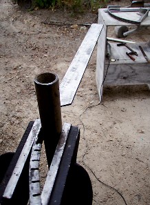
 I clamped the angle iron in a vise together with a length of 25mm (1-inch) steel pipe at the measured point. The pipe was at right angles to the angle iron and served as a form around which I bent the angle iron. To add leverage, I slid a 1-meter length of 60mm-ID pipe over the angle iron. As I worked, I checked the shape frequently against the outline drawing.
After repeating the procedure to form the second bend, I placed the frame on the 6mm flat plate (that would become the strongback) to ensure it was all in the same plane.
Making the boss clamp
 My rudder stock has an outside diameter of 2 inches, so I used a 3-inch length of 2-inch-ID pipe with a 4mm wall thickness for the boss clamp. The idea was to slice the pipe in half lengthwise and layer the two halves to form the boss section. By doing this, I could cut the keyway in the inner layer without using a lathe.
At the same time, I cut another 3-inch length of the 2-inch-ID pipe and sliced it, too, in half lengthways. I would use one half later when making the rear boss clamp.
For the keyway, I marked an area 10mm wide x 50mm high in the center of one pipe half, then made two parallel cuts with a hacksaw. I finished the keyway by drilling a 10mm hole at the bottom of the hacksaw cuts. I practiced a few dummy runs with the hacksaw, cutting on the waste side of the scribed line and filing the slot to size.
I made the two boss flanges from 75- x 10mm flat plate and tack welded them to each side of the keyed boss (half pipe). When I was satisfied everything was true, I fully welded the flanges in place, taking care to avoid distortion.
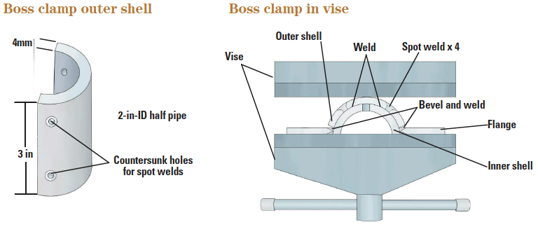 The second half-pipe provided the outer shell of the keyed boss, closing the third side of the keyway. To allow it to fit snugly against the keyed boss, I had to trim and bevel it to fit between the flange plates. Once I’d trimmed it, I drilled and countersunk four holes in it, two on each side of the keyway area but well away from it. These holes provided apertures for spot welds. I used a 6mm drill bit for the holes and a 10mm bit for the countersink.
I offered the second half-pipe to the keyed boss, clamped the two together in the vise, and closed the vise until they touched all around the perimeter, then welded them together all around the perimeter including to the flange plates. To avoid obstructing the keyway, I did not weld inside the keyway or around the top of it.
Using low power on the welding gun, I welded through the spot-weld holes to add further adhesion and reinforcement between the two half shells. The boss, with its 8mm wall thickness and 4-x 10-x 50mm keyway, was now complete. After grinding and dressing the excess weld, I drilled four 11mm holes in the flange plates to take the 10mm bolts that would fasten the boss to the quadrant.
Throughout the welding process, I allowed the work piece to cool down between weld runs to minimize distortion.
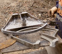
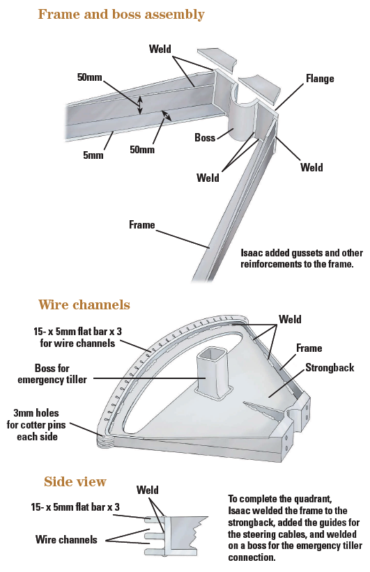
Isaac added gussets and other reinforcements to the frame.
Frame and boss assembly
I positioned the angle-iron quadrant frame and the boss clamp over the plywood drawing, marked the frame at the correct length and angle for fitting it to the boss clamp, and cut it accordingly. I then placed both components on the 6mm steel plate so as to have a flat base on which to assemble the two parts.
After aligning the quadrant frame and boss clamp to tally with the original quadrant, I tack welded them together, then checked the alignment again. I found the best way to check the alignment was to fit the assembly temporarily to the rudder stock. This also allowed me to make sure the quadrant would be properly aligned on the stock. When I was sure this was so, I completed the welding, working in sequence and taking breaks to minimize heat distortion.
To further reinforce the quadrant, I added a few extra gusset plates to the joints between the keyed boss, the frame, and the strongback.
Strongback plate
After making an accurate template of thick paper for the inner shape of the quadrant, I transferred the outline onto the 6mm steel plate. I also marked a cutout slot for the rudder-stop bolt. I then used an angle grinder to cut out the strongback and the slot for the rudder stop.
I inserted the strongback plate into the quadrant frame from the top, then welded it intermittently, top and bottom, around its perimeter to the frame and to the boss. To keep distor- tion to a minimum, I used weld runs up to 30mm.
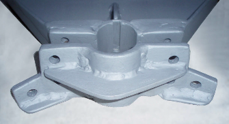
Cable channels
 I used three pieces of 15-x 4mm flat bar to make two channels for the steering wires on the outside of the quadrant arc. So I could bend them, I slotted each piece on one side with a disc cutter.
When I’d formed all three bars, I welded them to the quadrant’s outer arc, the top and bottom ones first then the middle one. I used offcuts to complete the ends of the channels so they wrap around the corners of the quadrant, and drilled 3mm holes in the corners to accept cotter pins to keep the cables in the channels.
Once the welding was complete, I used a disc grinder to remove the excess weld material from the channels and provide a smooth passage for the steering cables.
Finishing touches
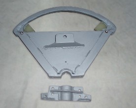
I fabricated the rear boss clamp, which attaches the quadrant to the rudder stock, in the same manner as the keyed boss clamp. Because it requires no keyway, I did not have to use a double thickness of the 2-inch-ID pipe, which made the fabrication simpler. Now both halves of the boss were complete, I drilled 11mm holes through them for the 10mm bolts that would clamp them to the rudder stock, and holes for the steering-cable tensioning bolts.
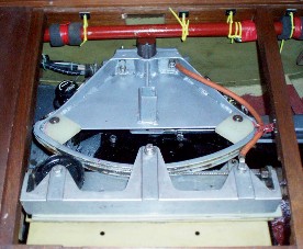
The emergency steering on Rhythm is incorporated in the quadrant. To accommodate this, I welded a square box-section stub to the top center of the strongback plate.
I also added a bracket to which to connect the autopilot drive arm and an anchoring point for the autopilot’s rudder indicator.
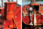
To protect the quadrant, I dipped it in hydrochloric acid, then washed and painted it. Galvanizing would have been a suitable alternative.
Anyone with basic skills could fabricate the parts for a quadrant in a similar manner, and someone with no knowledge of welding could hire that work out to a welding shop. Much of the metal cutting could also be hired out.
We fitted this new quadrant in July 2010, while we were in Australia, and it steered Rhythm back home to England. It is robust and should last a lifetime. The weakest point in the system is the steering cables, which, after all, are consumables.
Materials and Tools
Steel
Pipe: 2-in-ID x 4mm wall thickness
Angle iron: 50 x 50 x 5mm
Flat bar: 75 x10mm
Flat bar: 15 x 4mm
Flat plate: 600 x 600 x 6mm
Consumables
Welding rods: 2.5mm x 1kg
Grinding disc: (8 in)
Cutting discs: (4 in) x 5
I also used some scrap steel pipe and plywood that was lying around the house as formers and templates.
Total cost of materials and consumables in Australia in 2012: $60
Tools
Angle grinder, power drill, hammer, vise, hacksaw, arc-welding set, tape measure, files.
Construction time
Plenty! I view it as occupational therapy.
Isaac Adam-Azikri became a professional skipper in 1977, then retrained as a commercial diver and worked in the North Sea for 20 years. In 2013, he completed a 7-year circumnavigation of the world with his family aboard Rhythm, a Bill Dixon-designed 12-meter steel cutter.
Thank you to Sailrite Enterprises, Inc., for providing free access to back issues of Good Old Boat through intellectual property rights. Sailrite.com