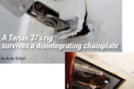
A timely prompt leads a DIYer to create new chainplates
Issue 152: Sept/Oct 2023
It all started because of a sailor named Ed, which is somewhat odd since I don’t even know Ed. But maybe I should backtrack a bit here. The story actually starts in June 2021, when we bought a 1984 Alberg 29. Those boats were built with stainless steel chainplates embedded in the hull’s fiberglass. The only visible bits are the tangs where the chainplates exit through the deck. It wasn’t a bad system — after all, those boats are turning 40 and I haven’t heard any story of failed plates.
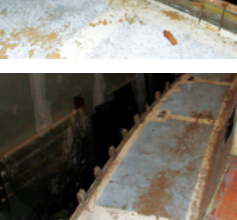
On the other hand, these boats are indeed turning 40. Since there is no way to inspect or test the chainplates, that leaves two options: Wait for their eventual failure — which could be tomorrow or in another 40 years — or replace them before that happens. And no matter how much Sikaflex sealant I used, a constant trickle of rusty-looking water from a small hole in the fiberglass inside the hull near the plate assembly kept whispering to me that one day I should do something.
Which brings me back to Ed. In the January/February 2023 issue of Good Old Boat, there is a very good article by Ed Zacko on chainplate inspection and metallurgy. The article is instructive, but it doesn’t necessarily help the owners of boats with old, hidden, stainless steel chainplates to sleep soundly. The close-up pictures of cracked stainless in Ed’s story convinced me to replace our chainplates with new, externally bolted ones.
From a DIY machining perspective, chainplates pose two main challenges. First, there are a lot of holes to drill, and ideally, they either need to be filed square for carriage bolts or countersunk for machine screws. It’s not impossible to do this in stainless with commonly available tools, but it sure is a lot of work. Second, the chainplates need to be bent to shape, and this is tricky if one wants to make sure not to cause stress that would affect the mechanical properties of the metal.
After talking it over with a few people, it dawned on me that the solution might be to use bronze. Our boat has classic lines and lots of bronze, including portholes, winches, cleats, and more — so externally bolted bronze chainplates would fit right in. Bronze is also easier to drill than stainless and can, with some caution, be cold- or heatbent without problems.
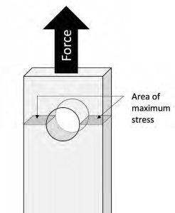
Once that decision was made, the next step was to figure out the sizing and design of the new plates. The main force exerted on a stay chainplate is upward through the stay cable. Design-wise, the plate needs to resist being stretched or ruptured by that tension and remain safely connected to the hull. The first part relates to the plate’s tensile strength, and the second to shearing stresses.
To figure out the theoretical tensile strength of a metal part, you first need to compute the area where there is the least amount of metal exposed to the full tension forces. In a chainplate, this weak point is likely at the tang hole or at the topmost bolt hole. To estimate its strength, you should measure the area of the weakest point in square inches and multiply it by the average tensile strength of the metal used in pounds per square inch.
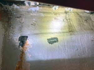
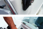
started shows a rusty drip at the corner of the embedded chainplate assembly.
Tensile strength also comes in two flavors — the yield strength and the breaking strength. The meaning of the latter is easy to figure out, but the former is the most important to consider. The yield strength is the stress at which a metal part will start to permanently deform. A metal part repeatedly exposed to forces close to or exceeding its yield tensile strength will fail relatively rapidly through metal fatigue, so the goal is to keep the stress on chainplates far below their yield strength.
The other force at play is shearing. This is about keeping the chainplates firmly attached to the hull and is what will drive decisions regarding the number of bolts and their size. Think of it this way: If the bolts were made of a soft material, as the stays pull upward, the bolts would be cleanly cut at the hull-chainplate junction, as by scissors. Precisely computing shearing forces implies many parameters, such as friction between parts, that are hard to estimate. One often quoted rule is to use 60% of a part’s tensile strength as an estimate of its shearing strength.
In reality, however, the bolts aren’t really exposed to the full shearing stress of the rigging, since the chainplates are pressed hard against the hull and are actually glued to it, which considerably increases the friction.
Despite all the jargon in the previous paragraphs, computing theoretical properties of metal parts isn’t that hard. However, the other side of the equation, which involves some seriously sophisticated engineering skills that I don’t have, is to figure out what forces are exerted in real conditions on a given boat. To circumvent my ignorance, I designed the chainplates so that their tensile yield strength and the bolts’ shearing resistance would both exceed the breaking strength of the stay cables. In other words, if the rigging were to be exposed to a degree of stress that the stays would break, the chainplates would still not have yielded or sheared.
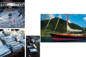
For my project, I decided to go with 3/8-inch thick and 1 ½-inch wide rectangle bars in 954 bronze, each with a bolt pattern of four 3/8-inch bronze machine screws. The shroud chainplates would be 20 inches long and the backstay ones 18 inches. If my computations aren’t too far off, the new system should be way stronger than the shroud cable breaking strength.
After comparing local prices with online suppliers, I ordered the bronze online. Rectangle bronze bars are cast and sold as is. This means that they are far from smooth and quite a bit larger than their nominal size to allow for finishing. Out of the box, the nominal 3/8-inch bars were closer to ½-inch thick, with some significant surface irregularities and pitting.
As a side note, bronze has the reputation of being a soft metal, and it is indeed easier to work with than stainless or hardened steel. However, after many hours spent working on the chainplates, I have a new respect for 954 bronze. It might be softer than some metals, but my pile of burned-out jigsaw blades and sanding discs is testament to the fallacy that bronze is soft. Bronze is also naturally somewhat self-lubricating, and this makes it quite resistant to cutting and sanding.
Machining-wise, the first step was to cut the plates to length. Straight cuts and bevels are easy with a circular miter saw and a good non-ferrous metal blade. Then I rounded the tang ends of the plates with a jigsaw. That part of the work was slow and somewhat frustrating. I then gave the plates a first rough polishing and deburring using a grinder and a hard disc.
Initially, my plan was to taper the plates’ thickness from 3/8 inch to ¼ inch downward. However, some pretests on leftover bits quickly made me realize that this would be a monster task with the tools at hand. I often use an electric wood planer to cut aluminum, and it works surprisingly well, but that’s a no-go with bronze (ask me how I know). And even using a grinder with good discs would make it a colossal task.
What took up a large amount of time were the innumerable trips back and forth to the marina, which is luckily just a 15-minute bike ride from home. The design stage required triple-checking and measuring alignments and fit, both on the outside and the inside of the hull. For example, the chainplates need to align with the angle of the stays and this, in turn, slightly changes the curve of the hull that they need to adapt to. In the same way, the ideal bolt pattern would look nice from the outside and also clear obstacles on the inside. After clocking about a Tour de France equivalent in miles biked to and fro, and drawing and erasing a ton of pencil lines, I finally brought home some cardboard templates of the bends and hole pattern.
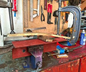
There are six shroud chainplates and two backstay chainplates on our boat. The shroud plates only needed a shallow bend to fit the shape of the hull and were cold-bent to shape. To do this, I built a jig out of a sturdy steel corner, some bronze leftovers used as chocks, and two large vises. The name of the game was patience. I clamped the parts, moved the chocks where it looked like some more bending was needed, and used one vise to push the bronze just past its elasticity point. Then I unclamped the plate, checked it against the template, and repeated the operation over and over. When everything looked fine, I did a real-life tryout against the hull and made some final adjustments on the jig.

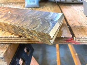
before heat-bending. The orientation of the future bend can be seen as a chalk line under the flame.
The backstay chainplates, however, needed one sharp bend of 30-odd degrees. This required heat-bending. If internet resources are to be trusted, the metallurgical properties of bronze aren’t too affected by heat if the part isn’t heated past a dull red. Having used bronze brazing extensively on bicycle frame building, I felt confident that it would be fine. I drew the desired bend as a chalk line on the plates and applied heat along the line with a propane torch. When the first traces of a reddish heat coloration showed, I rapidly aligned the chalk line with the vise jaws and clamped firmly before hand-bending it. As the plates were clamped in colder steel, the bronze was soft enough only for a few seconds at a time, so the final bend was achieved by multiple increments of about 10 degrees each.
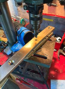
At that point, I gave the plates a more careful multistep sanding and started drilling. I bought a good quality drill bit that drills the hole and countersink in one step for flat head machine screws, something I definitely don’t regret. Eight chainplates with four bolts each make for long sessions with the drill press. Speaking of the drill press — a basic 8-inch Delta — it barely survived. Bronze isn’t that easy to drill. I had to limit myself to three or four holes before the motor started to smell funky and needed a long cooldown. Another tip I learned the hard way is that drill bits churn out an impressive amount of dangerously sharp bronze shards that will eventually end up everywhere. After a few sessions with my glasses and a pair of tweezers pulling shards from my hands, I finally figured out I should attach the vacuum tube to the drill press.
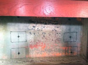
While the machining process went its slow, cautious way, I spent time preparing to install the plates on the boat. I decided to add a few layers of thick, woven fiberglass mat on the inside of the bulkheads where the bolts would be. The fiberglass was shaped to overlap about 6 inches on the central partition wall in front of the mast.
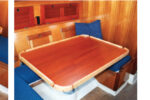
The plan was also to have G10 fiberglass backplates behind the nuts. However, with the embedded stainless of the existing chainplate system, somewhat rough handlaid original fiberglass, and my own additional layers, the challenge was that the hull’s inside was not flat. I thus had to individually carve and shape the backplates to fit their spots, and glue them with thickened epoxy.
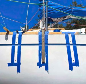
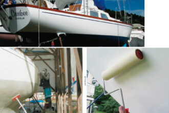
installed and the lower shroud ones are almost ready to be glued.
Then the big day came. We hauled the boat for some antifouling work and the chainplate installation. Drilling the pilot holes through the hull was stressful. Now that the backplates were glued in place, what if my alignments were off? There is no way those backplates would come off without grinding them down. I had tried multiple things to double-check the alignments. Strong magnets on both sides of the hull didn’t work because the hull is too thick. A small laser beam through the fiberglass didn’t work either, because the gelcoat is too opaque.
So I went with levels, rulers, and silent prayers, but my heart was racing when I climbed aboard to check the pilot hole exits. They were fine. The backplates are 3 inches by 4 inches, and all the holes were reasonably centered.
under tension.
I then slackened the two top shrouds and installed their chainplates, leaving the lower shrouds in place to make sure the mast would stay positioned. Drilling the hull’s fiberglass was easy work. Drilling through the embedded stainless within the hull, however, wasn’t; I discovered new shoulder muscles I didn’t even know I had before they started to ache.
I installed the plates for a dry run, then removed them. We added a generous amount of 3M 5200 adhesive sealant underneath and installed them for real after I sourced longer bolts, since the reinforced hull is over an inch thick at some places and my 2-inch bolts proved too short. We were lucky that a local shop had a few bronze screws — which aren’t that common — in stock.
We then retightened the top shrouds and installed the four lower shroud plates. Once all the shroud cables were tightened and the mast alignment double-checked, we moved to the backstay plates. Access to the inside of the hull was through two new round access hatches that I had to cut, which made the work a bit more challenging. I could either look inside the hatches or have one arm inside, but not both.
the chainplate oxidize and turn the same green as the portholes.
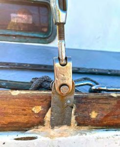
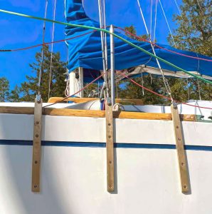
Overall, we’re really pleased with the look of the new chainplates and with the feeling we can trust them to keep our mast upright. The satisfaction of planning and executing a project on the boat is also always a reward, especially once the new bruises and scratches start to heal and the moments of rage and despair blur in one’s memory.
We will never know for sure if all that work was necessary. But I still think we owe Ed a sincere thank-you.
Astrid Brousselle and Damien Contandriopoulos sail from Victoria, British Columbia, usually with some or all of their three kids. Allamanda is Astrid’s second boat. The first was a 1975 Nordic Folkboat. There is a certain affection for old-school, long-keel boats that won’t ever back up where you want them to. But forward they’re fine. Really fine.
Thank you to Sailrite Enterprises, Inc., for providing free access to back issues of Good Old Boat through intellectual property rights. Sailrite.com