How to craft a DIY electrical panel
Issue 150: May/June 2023
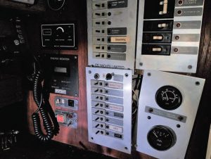
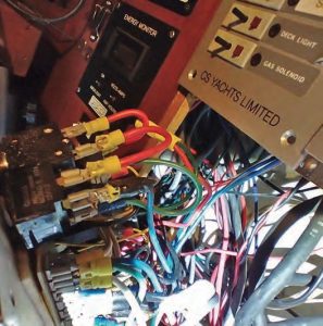
After our family’s C&C 35-3 Secret Plans was stolen (Good Old Boat September/October 2022), we purchased a new-to-us old boat and named her Plan B. She’s a 40-year-old CS-36 Traditional that has had at least four previous owners and logged some serious miles. As with most good old boats, Plan B came to us with an assortment of old and obsolete electronic bits, as well as some pretty dubious wiring done by the prior owners. The wiring was a rat’s nest of unlabeled wires and slide-on terminals. As an engineer who builds military electronics for a living, I found this unacceptable; it had to be replaced.
Besides a boat’s batteries, the heart of any electrical system is the main panel. From this, most electrical systems are controlled or at least power switched. I’d planned some extensive rewiring throughout the boat, so this was a logical starting point — bringing power from the batteries to the main panel and distributing it from there.
To design and fabricate a new panel, I planned the job in six steps.
1. Determine the size of the new panel and what switches need to fit and where, then draw a mockup of the panel.
2. Obtain a blank piece of aluminum and mark it for drilling.
3. Drill the holes required.
4. Paint.
5. Assemble and prewire.
6. Install it in the boat and hook it all up.
Sizing the Panel
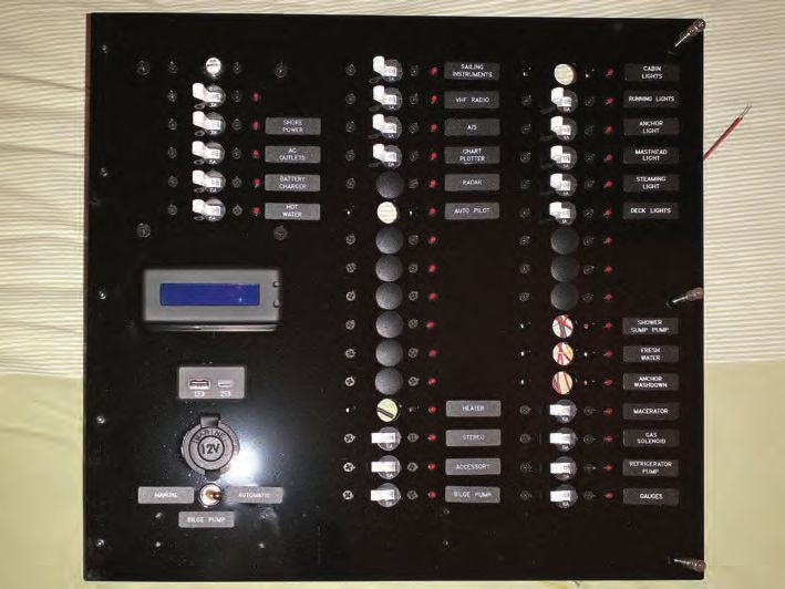
Determining how big a new panel should be can presumably be done by using the existing panel as a pattern, otherwise you have a hole to fill. I sized the panel to cover the entire area that had been occupied by various panels and bits of electronics. Keep in mind you can also break things up into several panels, as had been done originally on Plan B. Next, make a list of all the circuits that will be required on the panel. A good idea at the same time is to note the amperage needed so you can buy the right size circuit breakers. Then plan for a bunch of extra circuits that you don’t know you need yet — future you will thank you. In my case this meant a panel 16 inches by 15 inches, with AC main and three AC branches, 32 spots for DC circuits, a DC socket for accessories, a USB charging port, and a small N2K display. Do you want indicator lights? Any gauges? Now is your chance!
I then drew what the panel would look like at full size. It is easy to find the dimensions of components online. I had access to CAD software, but for our two previous boats I did this by hand on paper. Whatever your method, just be as accurate as possible, as this will be important later. The drawing doesn’t have to be dimensioned like mine; the key things are the center marks for the holes and the outlines for any cutouts like the USB charger. My drawing also included locations for mounting hardware — in this case a hinge on one end and some captive screws on the opposite edge. Simple mounting holes will suffice.
Sourcing Your Panel
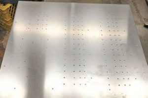
Finding an aluminum sheet of the size and thickness you’d like should be easy in most places where you’ll be working on your boat. Our local metal supplier happily sheared an 1/8-inch aluminum sheet to the specs I needed. I chose this thickness due to the relatively larger size of Plan B’s new panel. For a smaller panel, you can use a 1/16-inch thick sheet.
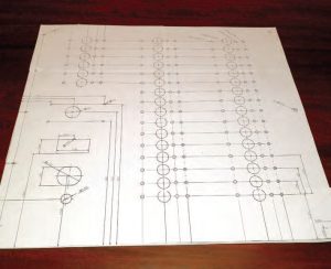
I then taped my full-size drawing onto the panel. Using a sharp center punch, I punched a mark through the paper for each hole that needed to be drilled. This is where a precise and accurate drawing comes in handy.
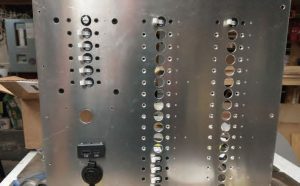
Drilling Holes
A job of this precision and scope is best accomplished with a drill press and sharp drill bits. Also, it shouldn’t be rushed, so budget several hours for this part of the project. For critical fit parts like indicator lights, it is best to drill a test hole in a piece of scrap and test fit the part to ensure the size is correct. I started by drilling the smallest holes first and working up to the larger holes on the basis that if I drilled in the wrong place, it would be a recoverable error as the hole would just be too small.
Painting the Panel
You can paint the panel with a paint type and color of your choice. I’ve previously used a hammered finish type spray paint and liked it; for this one I went more glossy.
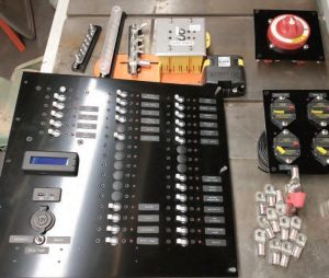
Assembling Components
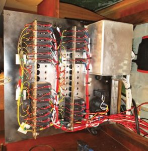
Once the paint had fully cured I assembled the components to the panel and prewired it. First, I fitted the hinge and the captive screws, then all the breakers, indicator lights, and accessories. From there, I prewired the panel, and there are a couple of things to note on this part. Best practice is to use a buss bar to connect all the “line” side terminals of the breakers. Line is the side of the breaker that power feeds into from the common source (the battery), so these terminals are all connected. A buss bar is a thick copper bar that acts as wires connecting the individual line side terminals. In my panel you can see two buss bars, one each on each column of circuit breakers. These are made of 1/8-inch by 3/8-inch copper, drilled so the screws for the terminals pass through. The lower end of the buss bar extends past the last circuit breaker and is drilled ¼-inch to allow attachment of a heavy-gauge power wire from the battery. These can be seen on the left side of the circuit breakers in the picture to the right, joined by the fat 8 AWG red wire. The connection to the battery will be made to the right buss bar, again with 8 AWG wire, at final installation.
On the red wire of each indicator LED I crimped a ring terminal; this is attached to the matching load terminal on the circuit breaker — the actual load wire will be installed later. The yellow wires of the indicator LEDs have to be gathered together and combined into one wire (in the picture it starts yellow but changes to black as I ran out of yellow). Where an LED wasn’t going to be attached to a circuit breaker I still put a ring terminal on the lead of the LED and then covered the ring with heat-shrink so that, when I need it later, it will be ready to go. If you do this, make sure you don’t use heat-shrink with adhesive in it. All of this wiring was then zip-tied in place. The bilge pump switch, accessory plug, and USB charger were also wired at this time and I used clamps for zip-tying the wires for wire management.
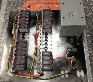
Also of note is the box attached at the upper right; this covers the AC shore power wiring. AC wiring is beyond the scope of this article; if you wish to include an AC section on your panel then be sure to lay out the breakers’ locations with enough free area around them to accommodate a covering box on the back of the panel. This is both an American Boat and Yacht Council (ABYC) requirement and is also common sense as the box is intended to ensure nothing short-circuits to your shorepower wiring. Connecting the actual shorepower wiring should be left to a professional.
Installing the Panel
And finally, installation in the boat — the main event! I first installed the frame for my new panel and fastened the hinge in place; this allowed me to have the panel partially open as needed. I wanted the wires to come down along the rows of circuit breakers and then off toward the hinge. Starting at the bottom, I cut the wires to length, labeled them, crimped on the ring terminal, and then attached them to the circuit breaker. I did use temporary zip ties on the wire bundle to ensure I was happy with how it ran. In this case there are wires coming into the panel area from three different directions so there are always going to be wires crossing, but trying to keep it neat was a priority.
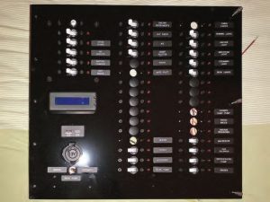
The new panel in Plan B has provided us with a season of trouble-free electrical work, and I’m already planning additions that will go in the empty spots.
Graham Collins is a mechanical engineer who builds anti-submarine detection equipment by day, runs a craft distillery after hours, and finds time here and there to work on Plan B, a CS-36T, and sail her in the waters of Nova Scotia.
Thank you to Sailrite Enterprises, Inc., for providing free access to back issues of Good Old Boat through intellectual property rights. Sailrite.com